! Matrix 832 / 832+ / 424
RINS428-5 Page 17
4.1 System Examples
A Matrix System is required to provide the following:
6 PIR Detectors (15mA each).
A bell-box (max. current draw 400mA) connected to PGM1.
2 Matrix ICON Keypads (60mA each), one 50m away, and the other 100m away.
A Matrix Transistor Output Expander (30mA) with 3 LEDs (10mA each) and 3 buzzers (12mA each) controlled
by the outputs (accompanying the keypad 100m away) power supply.
From the above example, the total current drawn from the panel would be:
TOTAL Detectors Bell RKPS
Output
Expander
LEDs Buzzers
0.706A 6 X 0.015 1 X 0.400 2 X 0.050 1 X 0.030 3 X 0.010 3 X 0.012
The maximum current available for external devices from the Matrix PCB is 0.6A. Therefore, this installation
would require an additional power supply.
Before we can calculate an acceptable wiring arrangement we must know the ‘KEN value for each device on
the keypad bus. From Table 1 we know that each keypad has a KEN of 1. The Transistor Output expander
controls the LEDs and buzzers, which together give a total current of 66mA (3x10mA + 3x12mA). From table
1 a transistor output expander with a current sink of 66mA falls into the <90mA criteria which corresponds with
a ‘KEN’ of 2.
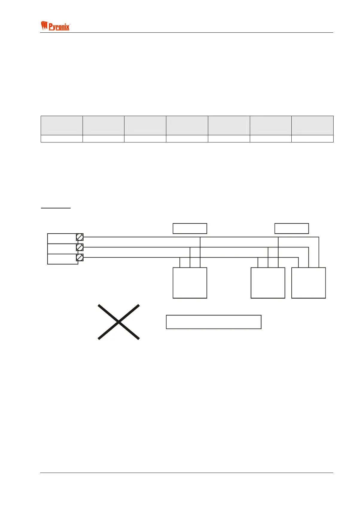
Example 1
The most straightforward wiring approach would be to daisy chain the devices on one run as below.
AUX+/K+
100m.
KD
AUX-/K-
Output
Expander
(2 KEN)
Keypad
2
(1 KEN)
Keypad
1
(1 KEN)
50m.
NOT ACCEPTABLE
However, this is an unacceptable solution because there are 4 ‘KEN’ on a 100m length of cable. Table 2
shows that a maximum of 3 ‘KEN’ is acceptable on a 100m length of cable – the fact that one keypad is just
50m away does not affect these rules.