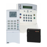
Matrix 832 / 832+ / 424
Page 16 RINS428-5
Section 4: Cabling Rules for the Matrix Bus
Care must be taken when connecting devices to the bus over long cable runs. This is to ensure maximum
system integrity under all circumstances (battery backup etc.). Pyronix recommends using standard 0.22mm
cross sectional area, unshielded multi-core alarm cable for Matrix installations.
The maximum number of devices connected to the bus on any one system is limited to six - this may
not be exceeded. Although six is the system limit other restrictions apply to each cable run. It is important to
restrict the amount of current carried along each length of cable to limit voltage drops across the system.
Apart from being affected by current magnitude, voltage drops are also dependent upon the length of cable
and the types of devices fitted.
The following tables provide a means of determining suitable cable run configurations for different systems.
NOTE: It is the length of cable between panel and end device that is important rather than the overall
length on the entire bus.
Table 1: ‘KEN’ (Keypad Equivalent Number) values for each serial module
DEVICE Description and Configuration KEN
MX-LCD Matrix LCD Keypad 3
MX-LED Matrix LED Keypad 1
MX-ICON Matrix ICON Keypad 1
MX-RIX with
Zone Analyser
Matrix Remote Zone Expander.
1
MX_PROX Proximity Reader 2
MX-ROX8R 8 Way Relay Output Module *1 *2 4
MX-ROX8T
8 Way Transistor Output Module (max. total transistor
outputs current sink < 30mA)
1
MX-ROX8T
8 Way Transistor Output Module (max. total transistor
outputs current sink < 90mA)
2
MX-ROX8T
8 Way Transistor Output Module (max. total transistor
outputs current sink < 150mA)
3
MX-ROX8T
8 Way Transistor Output Module (max. total transistor
outputs current sink < 210mA)
4
Sink Current(A) – 0.03
MX-ROX8T
8 Way Transistor Output Module (max. total transistor
outputs current sink > 210mA)
1+
0.06
*1 The Above KEN assignments for Relay type output modules assume that all power supplying the switched
contacts (devices switched on/off by the output expander) is supplied via a different feed/ PSU.
*2 Remember that the maximum allowable current-draw from the Matrix for External devices is 0.6A. Any
requirement exceeding this must be provided by a separate power supply. Where a power supply is added for
use with an output expander, the 0V of the supply should be connected at the expander. 1+
Table 2: Number of ‘KENs’ Allowed for different Cable lengths.
Length of Cable
(meters)
Number of KEN allowed with Single
core cable per signal
Number of KENs with standard
cable 0V return doubled (2 cables)
100 3 4
75 4 6
50 6 9
25 13 18

 Loading...