! Matrix 832 / 832+ / 424
RINS428-5 Page 71
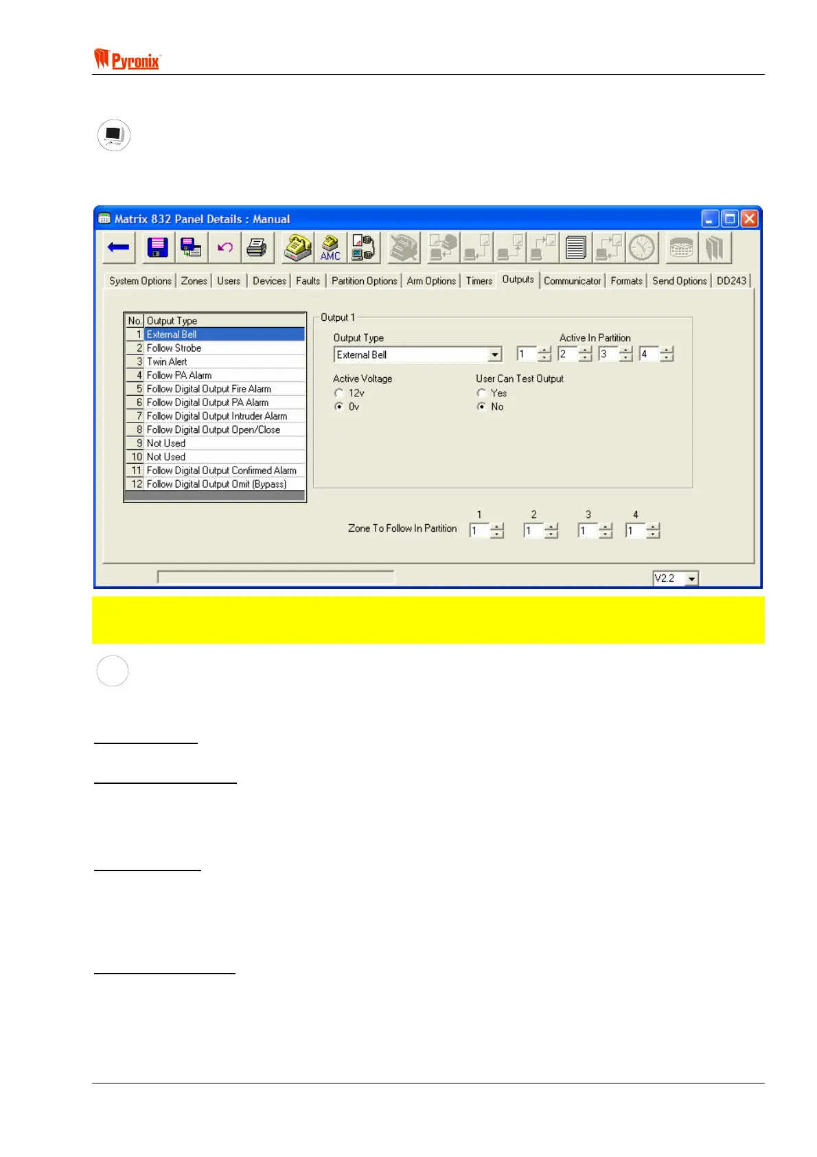
7.14 Programmable Outputs
PC Programming Procedure
The PC window below shows how to program output options and allocated partitions from PC software. Once
an option has been chosen press the <save> button and proceed to the next window.
NOTE: This system has 4 PGMs (expandable to 12) that can be programmed to activate on occurrence
of different events and can be associated with one or more partitions. The polarity of these outputs
may be either 12V to 0V or 0V to 12V.
MEANING
Programmable Options Explanation
Output Types
[00] = Not Used.
Disable the output
[01] = E- (LED Enable)
This option will allow the PIR LED’s to be enabled during walk test mode if they have been originally disabled
by removing the link pin. When the system in walk test mode this output will emit 0V that will enable the LED.
On exiting the walk test mode the LED will be disabled. This option will only work if the detectors have a
remote LED enable facility (e.g. Pyronix Enforcer Super, Octopus Super, Equinox AM).
[02] = C+ (Latch)
This feature is used to reset the latch option of detectors that have this function. When the panel is armed the
LEDs of any triggered detector on the zone will latch causing their LEDs to flash on and off when the panel is
disarmed. Any time that an user code is entered the output will change state. To reset the latch enter user
code and within 5 sec enter it again. This feature will only work if the PIR has a latch memory facility (e.g.
Pyronix Enforcer Super, Octopus Super, Equinox AM).
[03] = RKP Controlled
This option operates a 5 seconds switch output. Enter BTY
on an Icon Keypad or select the appropriate
option from an LCD keypad from master user mode. The output will change state for 5 seconds. It may be
used, for example, to electronically unlock a door.