Matrix 832 / 832+ / 424
Page 8 RINS428-5
CENTRAL MONITORING OPTIONS – Cont.
Group Reporting to CMS
1. Events sent to 1 number only
2. Events sent to 2 numbers
3. Events sent to first number with
backup of second number
1. Events sent to 1 number only
2. Events sent to 2 numbers
3. Events sent to first number with
backup of second number
Programmable Send
Options
1. In disarmed mode
2. In arm modes A, B, C and D
3. Restorals
4. Alarms
5. PAs
6. Fire
7. Maintenance
8. Open / Close
9. Medical
1. In disarmed mode
2. In arm modes A, B, C and D
3. Restorals
4. Alarms
5. PAs
6. Fire
7. Maintenance
8. Open / Close
9. Medical
Test Call
Programmable in days, hours and
minutes
Programmable in days, hours and
minutes
Telephone Line Monitoring
Yes – with status indication Yes – with status indication
Telephone Connection
Allows other telephone on the line Allows other telephone on the line
Digital Communicator
Analogue line Analogue line
Lightning Protection
Heavy duty lightning protection
6.75kV/125Amps
Heavy duty lightning protection
6.75kV/125Amps
OTHER
Software Support
1. UDL programming software
2. Pyronix MX-MON software to be
used with:
a. Modem + Pyronix format
b. RC12/RC112 +
Contact ID/BSIA
1. UDL programming software
2. Pyronix MX-MON software to be
used with:
a. Modem + Pyronix format
b. RC12/RC112 +
Contact ID/BSIA
Memory Event Log
300 events with time and date
Log deletion cannot be allowed either
accidentally or on purpose.
Log reaction time is more than 30
days and the clock will not change
more than + / - 10 mins over 1 year at
20c
300 events with time and date
Log deletion cannot be allowed either
accidentally or on purpose.
Log reaction time is more than 30
days and the clock will not change
more than + / - 10 mins over 1 year at
20c
1.3.1.1 Minimum Installation Requirements
In addition to the main alarm panel (424, 832 or 832+), and any detectors or sensors, at least one keypad is
required. This can be an LCD, LED or ICON keypad. One keypad MUST be set to ID-1. This is the minimum
requirement.
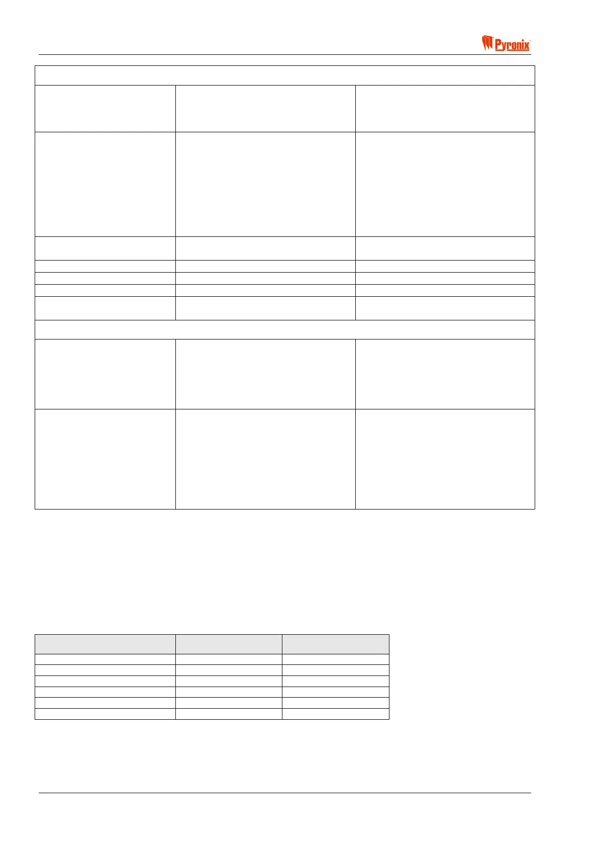
1.3.1.2 Installation Constraints
A maximum of 6 devices can be attached to the Matrix bus (see also Section 4: Cabling Rules for the Matrix
Bus). The following table shows the maximum number of each device type allowable, whilst at the same time
remembering that only 6 devices in total can be on the bus at any one time.
BUS DEVICE MATRIX 832+ /832 MATRIX 424
LCD Keypad 4 4
ICON Keypad 4 4
MX-PROX Proximity Reader 4 4
MX-RIX with Zone Analyser 1 1
On-board Input Expander 1 1
MX-ROX Output Expander 1 1

 Loading...