SECTION 3
OPERATING PRINTER
18
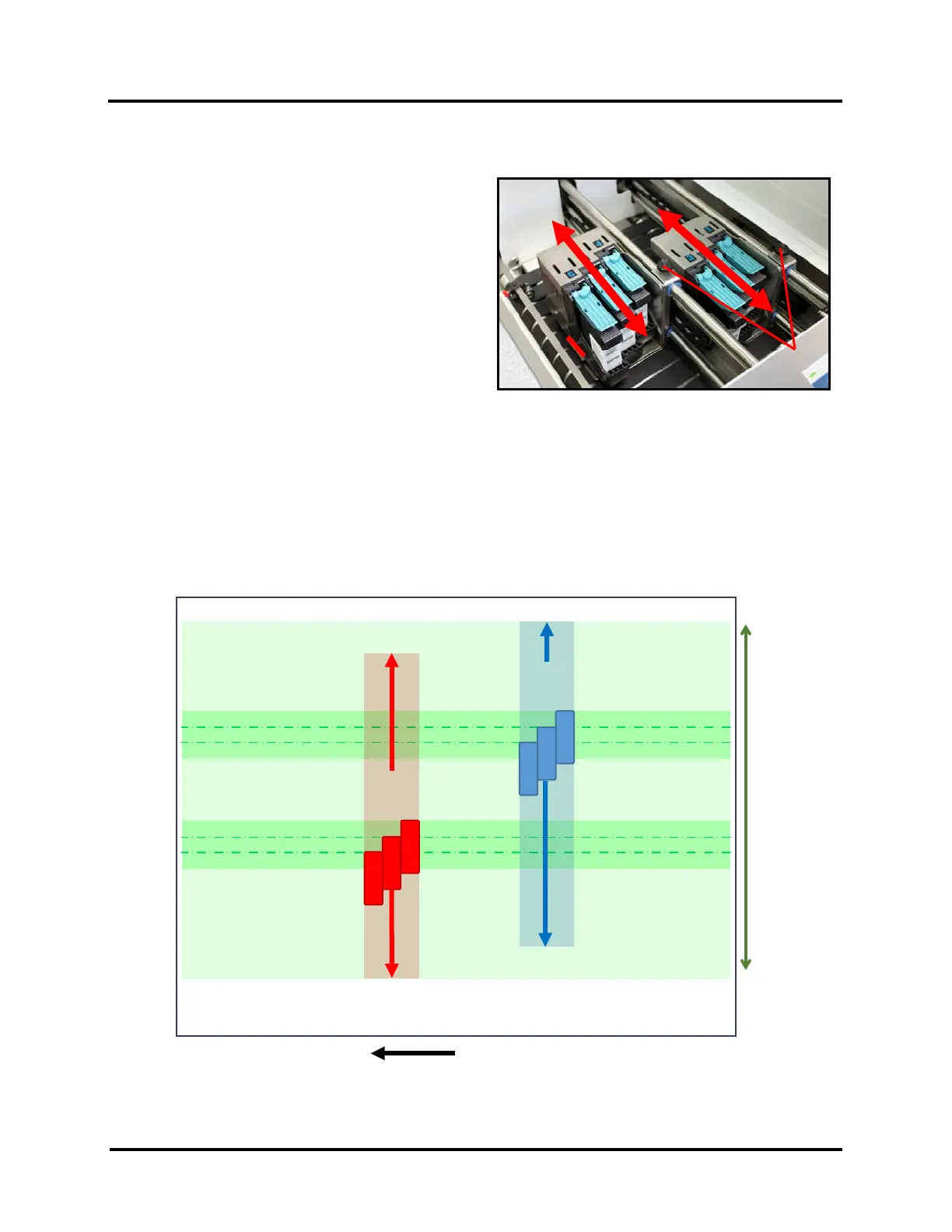
Position Print Units
1. Loosening locking screw(s) [A].
2. Position Print Units as needed to print on media
being fed.
TIP: Print Area Indicators are provided at the exit
side of the Print Units. This is useful when trying to
achieve the desired print position for the Print
Units.
3. Secure locking screw(s) [A]
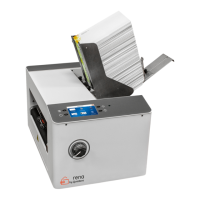
Print Range
The sketch below shows the range of each Print Units movement.
It also indicates the “No Print Zones” (unreachable print areas) when feeding the Printer’s maximum Media size of
13.5” Width x 17” Length (in direction of feed).
When feeding Media measuring 11” wide, or narrower, it is possible to position the combination of Print Units to
print anywhere within the width of the Media.
MAX PIECE 13.5” W
MAX PRINT RANGE: 11”
10”
VERTICAL
RANGE
10”
VERTICAL
RANGE