64 Chapter 12 CEC Interactive Troubleshooting Environment (ITE)
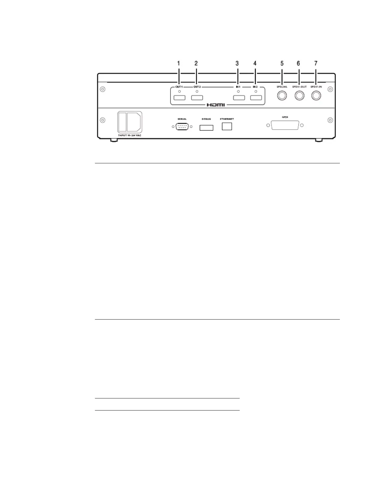
The video interfaces on the 882EA are shown below.
Emulating an HDMI CEC device
The 882 generator has two HDMI OUT(Tx) connectors. Either one can be configured to
emulate an HDMI CEC source device. There are two HDMI Rx connectors on the 882CA
analyzer option. Both these outputs are configured together to emulate a single HDMI
CEC sink device. The mapping of these connectors to an emulated CEC device type is
shown in the following table:
Interface Description
1 HDMI OUT 1 connector outputs full single link HDMI 1.3 video, as well as DVI and
modern HDMI-compatible digital video signals.
2 HDMI OUT 2 connector outputs full single link HDMI 1.3 video, as well as DVI and
modern HDMI-compatible digital video signals.
3 HDMI IN 1 connector accepts full single link HDMI 1.3 video, as well as DVI and
modern HDMI-compatible digital video signals.
4 HDMI IN 2 connector accepts full single link HDMI 1.3 video, as well as DVI and
modern HDMI-compatible digital video signals.
5 SPECIAL connector provides multiple outputs, including:
• digital composite sync
• line sync
• frame sync
• movable scope trigger (probe) pulse
• pixel clock signal
6 SPDIF OUT connector outputs audio to an external receiver.
7 SPDIF IN connector inputs audio from an external source.
HDMI Tx Out1 HDMI Tx Out2 HDMI Rx In1/2
CEC1 CEC2 CEC3