882 Video Test Instrument User Guide (Rev A.35) 7
Computer interfaces
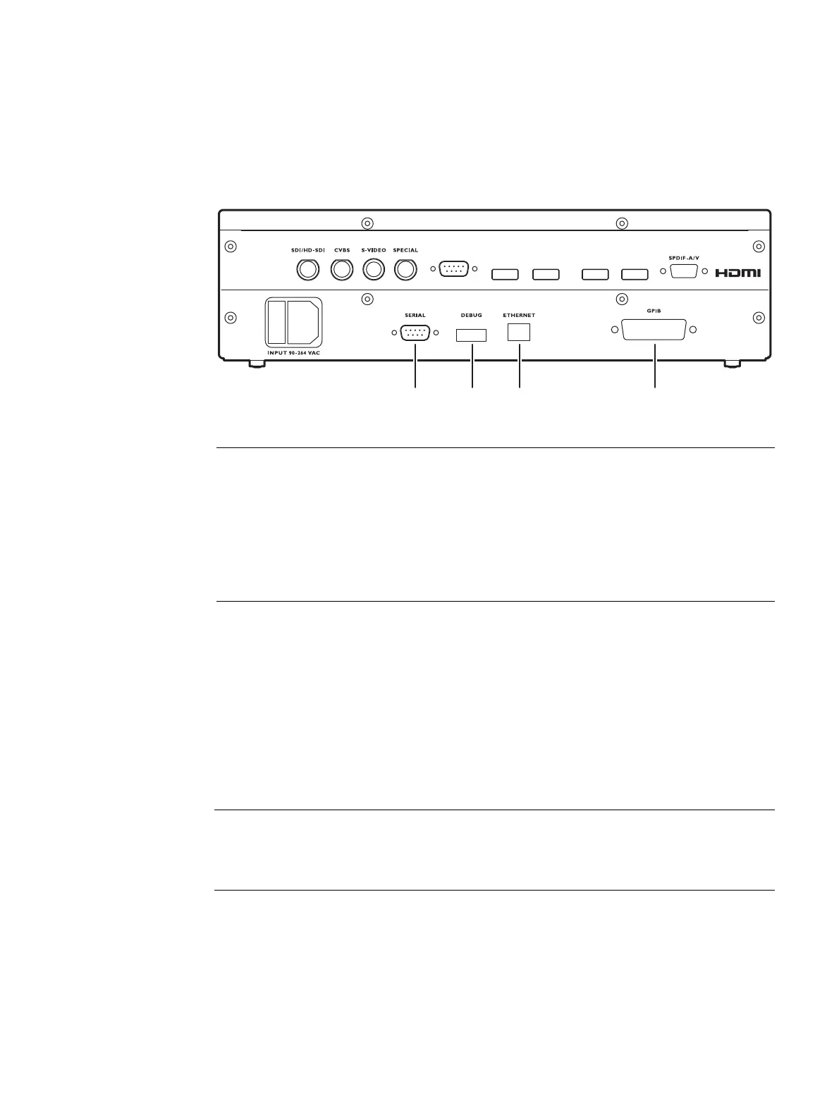
This section describes the 882’s computer interfaces. The computer interfaces are shown
below (882C shown).
RS-232 interface
Each 882 has a standard RS-232 serial connector, labeled “SERIAL.” This is a 9-pin
D-Sub male connector which enables you to connect the 882 with a computer. A null
modem cable is provided to support this interface. You can communicate with the 882
through the command line interface using a terminal emulator such as HyperTerminal. For
more information, see “Working with the serial interface” on page 30. The pinouts for the
RS-232 connector are shown in the following table.
Connector Description
1 SERIAL connector provides RS-232C serial data communication interface for the
882.
2 DEBUG connector is for Quantum Data use only.
3 ETHERNET connector is used to connect the 882 with a TCP/IP network, for
remote administration and control, and for sharing resources from a file server.
4 GPIB connector provides IEEE-488 GPIB interface to the generator (882 only; not
provided on 881 generators).
Pin Signal Pin Signal Pin Signal
1 Data Carrier Detect 4 Data Terminal Ready 7 Request to Send
2 Received Data 5 Signal Ground 8 Clear to Send
3 Transmitted Data 6 Data Set Ready 9 Ring Indicator
HDMI OUT 1
HDMI OUT 2 HDMI IN 1 HDMI IN 2
VGA
123 4