40 Chapter 2 Testing Video Displays
General video display testing procedures
This section provides an overview of basic steps performed to test your video display
using your 882 or 881. Testing your video display involves four basic steps:
1. Connecting 882 to display under test.
2. Selecting interface type for display under test.
3. Selecting a video format appropriate for display under test.
4. Selecting an image suitable for testing the display under test.
Making physical connection
The first step is to make a physical cable connection between the 882 and display under
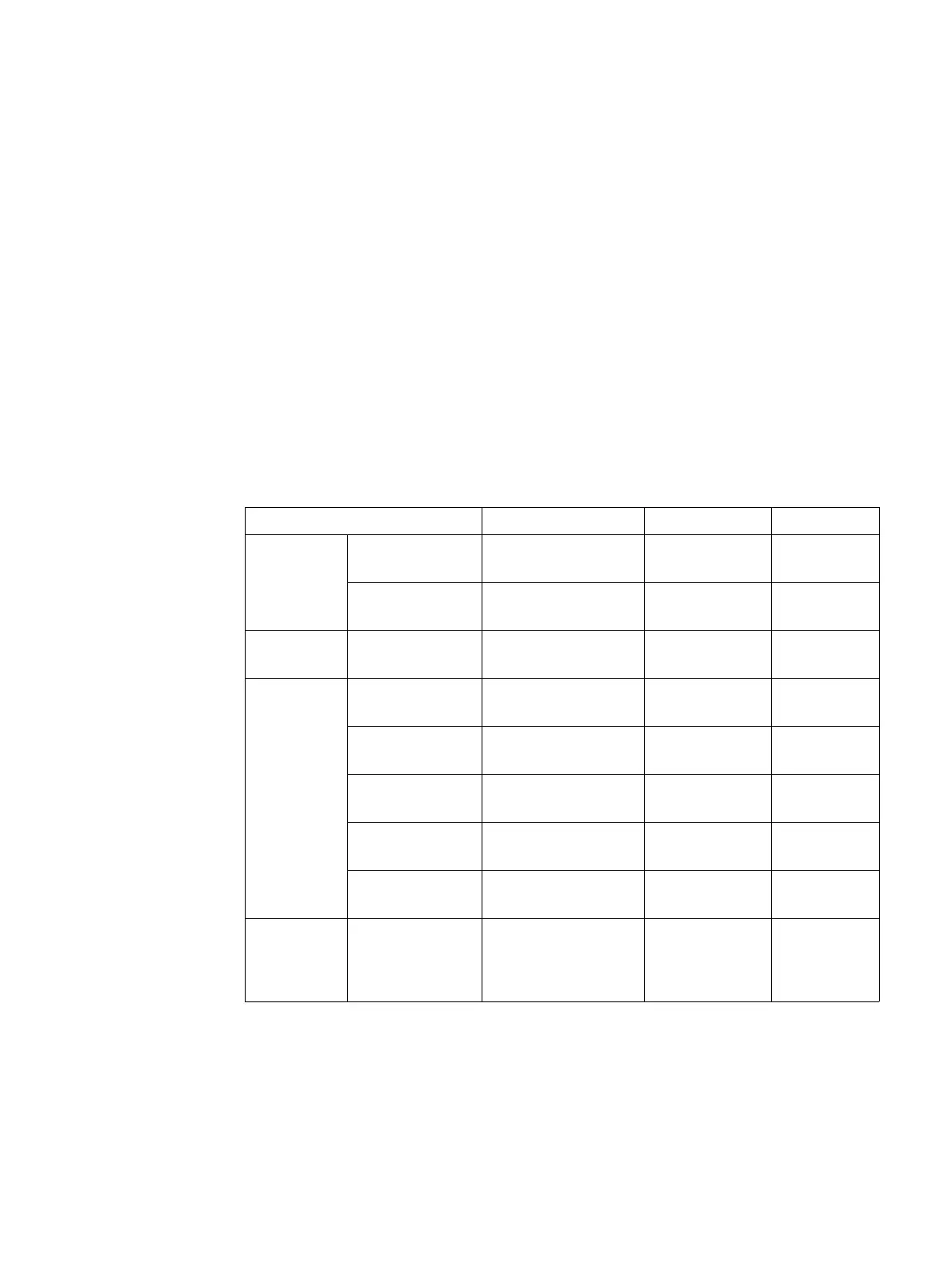
test. The following table provides guidelines for connecting the 882C, 882E, 881C or 882E
generator to the display under test.
Display type Signal type Port (Interface) Cable
Information
Technology
(IT)
Computer - VESA
(DMT, CVT)
Analog component
RGB
VGA VGA to VGA
Computer - VESA
DDWG
Digital component
RGB
HDMI OUT
(HDMI-D)
HDMI to DVI
DisplayPort
(882E only)
Digital component
RGB
DisplayPort OUT DisplayPort
Consumer
Equipment
(CE)
SDTV - ITU-470-6
baseband
Analog composite
CVBS
CVBS BNC to RCA
75 Ohm
SDTV - ITU-470-6
baseband
Analog composite
S-Video
SVIDEO S-Video
(miniDin)
SDTV - CEA-861B Analog component
YPbPr
VGA VGA to RCA
1
1. Optional cable available from Quantum Data.
HDTV -
CEA-861C
Digital component DVI
RGB
HDMI OUT
(HDMI-D)
HDMI to DVI
HDTV -
CEA-861C
Digital component
HDMI RGB and YCbCr
HDMI OUT
(HDMI-H)
HDMI to HDMI
Professional
AV
SDI
(SMPTE-259M)
and HD-SDI
(SMPTE-292M-C)
Digital component
YCbCr
SDI/HD-SDI BNC Coax