43
©2006 Sunrise Medical
QUICKIE ELECTRONICS SECTION
Joystick Housing Replacement
Turn off Joystick and unplug 1.
Remove the Joystick from the Joystick Mount2.
Remove the four T 10 torx screws from the bottom 3.
case of the Joystick (fi g 2.7.1)
Remove the bottom case If bottom case is equi-4.
ped with jacks or switch and potentiometer then
remove the six pin connector if applicable
Remove the eight pin connector by pulling from 5.
the circuit board (fi g 2.8.1)
Remove the four T 10 torx screws securing the 6.
joystick mechanism retaining ring (fi g 2.8.2)
Remove the joystick mechanism, retaining ring, 7.
hood and knob
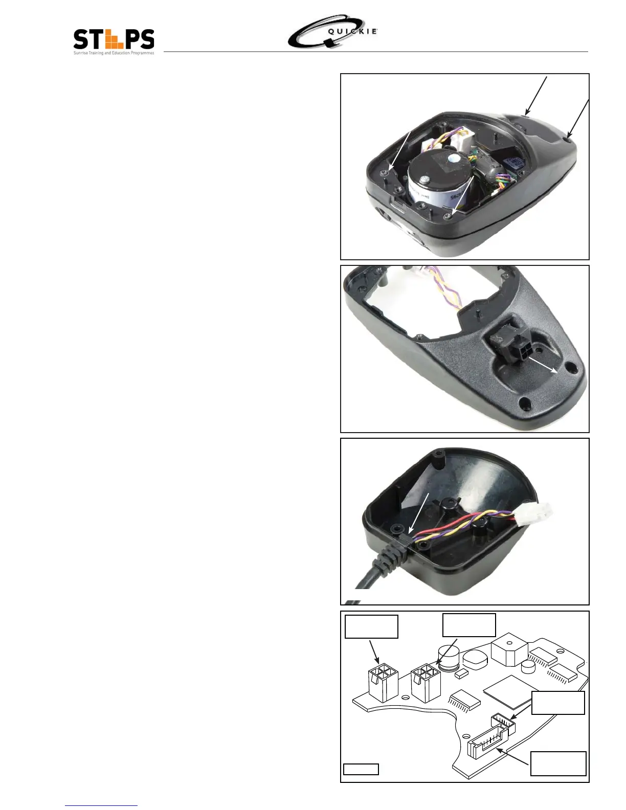
Remove the four T 10 torx screws securing the 8.
upper and middle housing (fi g 2.9.1)
Remove the circuit board9.
Remove the com-port connector and boot by 10.
pushing the boot out from the inside of the middle
housing (fi g 2.9.2)
It may be necessary to disassemble middle and 11.
top housing of the new joystick housing
Insert the com-port and boot from the outside into 12.
the new middle housing and pull the boot fl ange
tight against the middle housing
Insert the joystick mechanism in the upper hous-13.
ing and align the retaining ring with the four holes
reinstall the four T10 torx screws
Insert the circuit board on the three location pins 14.
of the new upper housing
Align the upper and lower housings and make 15.
sure the rubber gasket is properly seated then re-
install the 4 T 10 torx screws
Re-connect the com-port connector, the eight pin 16.
joystick mechanism connector and the six pin heel
controls connector if equiped (fi g 2.9.4)
Insert the strain relief of the fl ying lead into the 17.
bottom cover (fi g 2.9.3) and re-connect the four
pin connector (fi g 2.9.4)
Make sure the rubber gasket is properly seated 18.
between the middle housing and bottom case
Install the four T 10 torx screws that secure the 19.
bottom case (fi g 2.7.1)
Fig 2.9.1
Fig 2.9.2
Fig 2.9.4
Flying Lead-
connector
Joystick Mech
8-pin connector
Heel controls
connector
comm-port
connector
Fig 2.9.3