EasyManua.ls Logo

Radwin 5000

Radwin 5000
139 pages
To Next Page IconTo Next Page
To Previous Page IconTo Previous Page
Loading...
RADWIN 5000 Installaon Guide
August 2023
112
Table 18: Frequency Band 2400‐2483.5 MHz WiFi
Cat. No.
Type
Gain (dBi)
Dir BW
Tx Power per
chain (dBm)
Min. Safe
Distance (cm)
On Board
Printed
3.0
360°
26
110
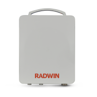
The RADWIN 5000 JET bears the following FCC/IC IDs on the label, and refer to Table 19 to Table 22 below:
FCC ID: Q3K‐BFJET5XT40 IC: 5100A‐BFJET5XT40
This radio transmier “IC: 5100A‐BFJET5XT40” has been approved by Innovaon, Science and Economic
Development Canada to operate with the antenna types listed below, with the maximum permissible gain
indicated. Antenna types not included in this list that have a gain greater than the maximum gain indicated
for any type listed are strictly prohibited for use with this device.
The input impedance of all antennas is 50 Ohm.
The RADWIN 5000 JET must be installed so as to provide a minimum separaon distance from bystanders as
specied in the tables below:
Table 19: Frequency Band 5725‐5850 MHz
Operang Form
Gain (dBi)
Dir BW
Tx Power per chain
(dBm)
Min. Safe Distance
(cm)
Uniform
20.0
9.4°
13
96
Floodlight
11.0
60°
22
96
Table 20: Frequency Bands 5250‐5350 MHz and 5470‐5725 MHz
Operang Form
Gain (dBi)
Dir BW
Tx Power per chain
(dBm)
Min. Safe Distance
(cm)
Uniform
20.0
9.4°
7
20
Floodlight
11.0
60°
16
20
Table 21: Frequency Bands 5150‐5250 MHz
Operang Form
Gain (dBi)
Dir BW
Tx Power per chain
(dBm)
Min. Safe Distance
(cm)
Uniform
20.0
9.4°
13
20
Floodlight
11.0
60°
13
20

Table of Contents

Other manuals for Radwin 5000

Related product manuals