24
CM
Edition 10-2008
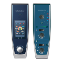
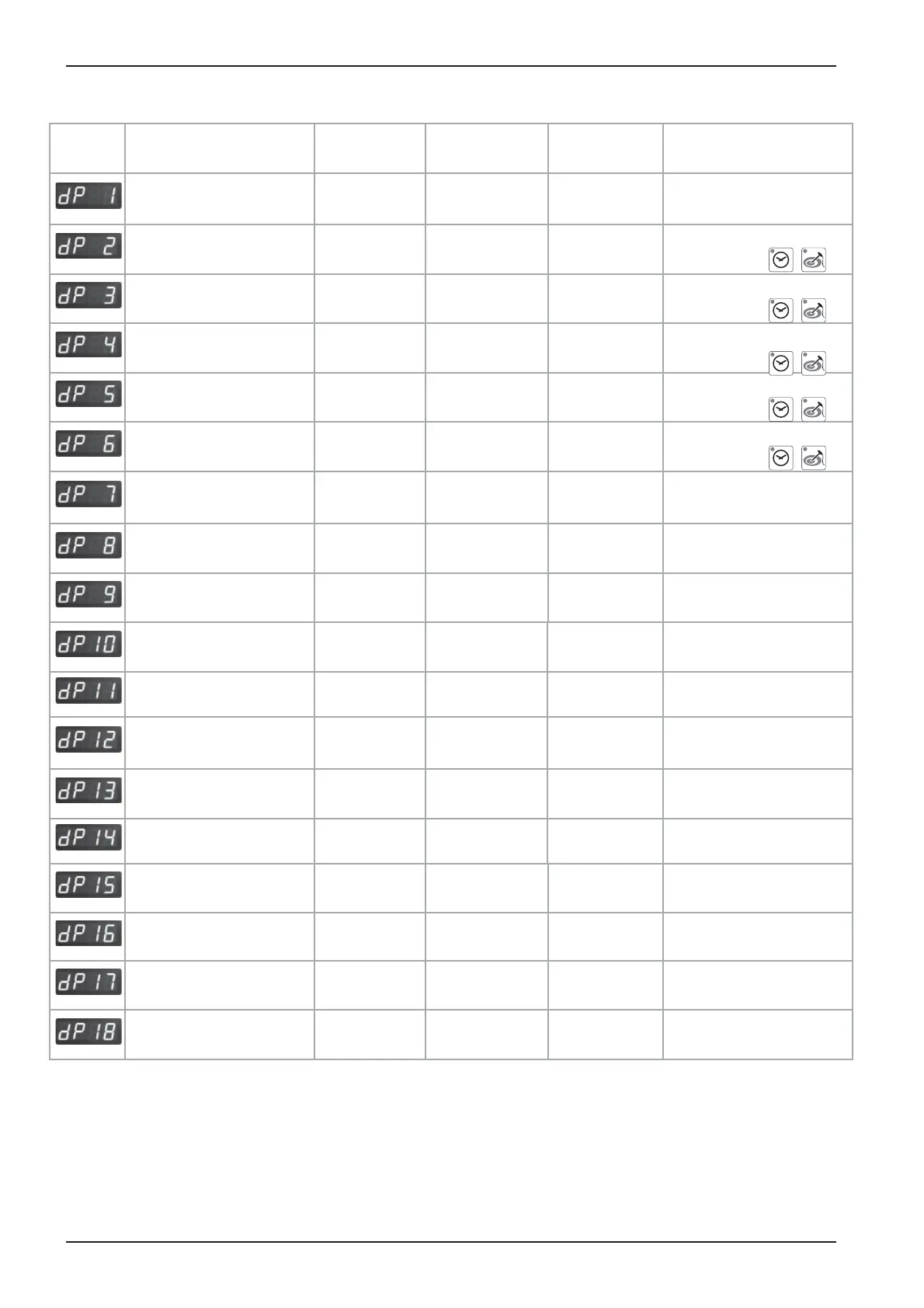
Service level: dP -- Diagnostic Program
Description Connection
Cabinet
Display
Time display
Software Version
Software
Version: C - 1
Software
07.01
B1 Cabinet sensor X 3 actual value max value
Reset by pressing
for 5 sec.
B2 Quenching sensor X 4 actual value max value
Reset by pressing
for 5 sec.
B3 Core sensor X 2 actual value max value
Reset by pressing
for 5 sec.
B5 Steam generator
sensor
X 6 actual value max value
Reset by pressing
for 5 sec.
PCB temperature actual value max value
Reset by pressing
for 5 sec.
S3 Door contact X27:(1-2) 1 - 0
0 = door open
1 = door closed
S2 Water level steam
generator
X12:(1-4) S2
X19:(1-3) Y1
S2: 0 - 1 Y1: 1 - 0
Steam elements
0 - off; 1 - 50%; 2 - 100%
actual Temp.
B5
0 - 1 - 2
Hot Air elements
0 - off; 1 - 50%; 2 - 100%
actual Temp.
B1
0 - 1 - 2
Speed fan motor bottom BUS Set rpm actual rpm
Speed fan motor top BUS Set rpm actual rpm
only oor model
201/202
Energy management
(Sicotronic)
X 20 1 - 0
SSR control (US version)
X24
1 - 0 0 = US version only
Unit size and type
61 - 202 ELE - GAS
Flame current Steam x.x A*
since SW Version:
C1-06-05 ( ame current)
Flame current Hot air
top
Hot air top
x.x A*
since SW Version:
C1-06-05 ( ame current)
Flame current Hot air
bottom
Hot air bottom
x.x A*
since SW Version:
C1-06-05 ( ame current)
*
With SW Version C1-06-05 the ame current will show as 20-24A
(This value must be divided by 4 to get the correct ame current e. g. 22:4 = 5,5A.)
Starting with SW version C1-07-01 the actual ame current is shown .
+
+
+
+
+