55
SCC
Edition 10-2008a
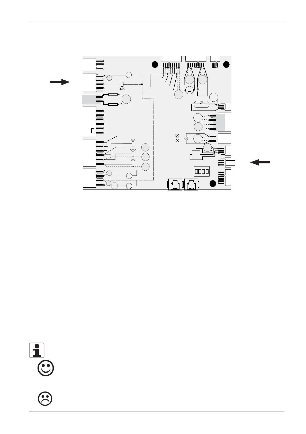
New I/O PCB SCC (42.00.064P)
Wires of pcb edge connectors are pointing to component side of pcb!
18: SC-pump M4, Cleanjet pump M6
19: Solenoid vales Y1- lling, Y2 - quenching, Y3 - moistening
20. Energy optimizing plug with link on 5-6 used only on I/O pcb with 12 relais card!
21. 230V input
75. Care pump M12 and Care solenoid Y4 (free when used in Index “E” unit)
23. Connection to Ultravent (used for Ultravent without BUS connection only)
24. Output 12VDC to SSR
25. Output 12VDC to M7 drain valve, S12 micro switch drain valve
26. free
27. Output 12VDC to door contact
14. Input from Control transformer T1, 11.5V interior light, 12V CPU,
13. Output 11.5VAC to interior cabinet light
15. Output 12VDC to CDS sensor
17. Link Care unit (only existing when build into an Index “G” unit)
16. free
X3, X4. BUS connection
LED Code: I/O PCB
Green LED on - ok
Green LED off during operation ok
Yellow LED always blinking: unit switched off, unit in booting process, DIP switches not all
set to OFF, bus connection defective
Green LED off: I/O PCB defectice, Transformer defective
S3
T1
K1:L1
F2: N
230 V
GND
IN
OUT
CDS-HALL
S12
M7
M
+
_
16 V DC
11,5 V AC
Y1
A1
A2
A1
A2
Y3
A1
A2
M4
M
~
M6
M
~
12 V DC
12 V AC
12 V DC
H1
11,5 V
AC
230 V
230 V
+ 12V
SSR1: A-
SSR1: B-
SSR2: A-
SSR2: B-
N
Y2
12 V DC
12 V DC
2A T
2A T
LED Gr
LED Ye
X 24.1
X 25.1
X 26.1
X 27.1
X 14.1
X 13.1
X 15.1
X 17.1
X 16.1
X 23.1
X 75
X 20.1
X 19.1
X 18.1
X 21.1
M12
M
~
230 V
A1
A2
Y4
Y1
230 V
Y3
230 V
Y2
230 V
ON
1234
18
19
20
21
75
23
24 25 26
27
14
13
15
17
16
X 3X 4