The rear axle Section K
3 Remove the drain plug and check that the
differential
unit
rotates freely.
4
Screw the
two
circular plates
of
the tool
R.T.
8732
onto
the push rods. Insert these
through the axle tube, ensuring that the swivel
pad on each end is felt
to
locate in each side
of
the differential carrier bore. Screw the plates
up
to the axle tube flange and secure
with
the
bolts supplied. Unscrew both rods slightly
before finally clamping the plate. The
two
round
knurled gauging nuts should
be
screwed onto
the push rod
which
is facing the crown wheel
or
pinion side
of
the crown wheel,
which
for
convenience
of
explanation should
be
on the
L.H. side
of
the operator
as
he faces the axle
and referred to
as
the L.H. side throughout these
instructions.
5 Unscrew the R.H. side push rod
approximately
i
inc.h
. Screw in the L.H. push
rod
with
a load
of
2-41bs
ft
maximum, thus
pushing the differential assembly over into the
R.H. housing. Screw
up
the gauging nut li
ghtly
to the face
of
the circular plate. Carefully and
securely
with
the other nut
lock
together, and
screw the push rod back approximately
i inch,
ensuring the gauge nuts move
with
the screw
as
they come away from the plate. Screw in the
R.H. p
us
h rod 2-41bs
ft
maximum thus pushing
the differential unit into the L.H. axle housing.
Screw in the
L.H
. push rod
unt
il
a stop is felt.
M
easu
re
the gap between the circular plate and
the gauge nut
with
feeler gauges and record the
figure (see
Figure
9)
which
represents the
overall end float.
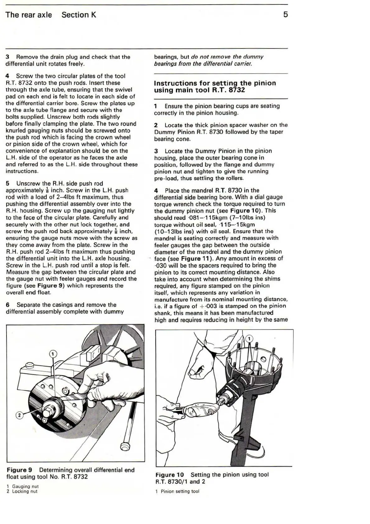
6 Separate the casings and
rem
ove the
differential assembly complete
with
dummy
Figure
9 Determining overall differential end
float using tool No. R.T.
8732
1
Ga
uging
nut
2 Locking
nut
bearings,
but
do
not
remove the dummy
bearings
from
t
he
differential carrier.
Instruct
ions
for
setting
the
pi
ni
on
using
main
tool
R.T
.
8732
1 Ensure the pinion bearing cups are seating
correctly in the pinion housing.
5
2 l ocate the thick pinion spacer washer on the
Dummy Pinion R.T.
8730
followed by the taper
bearing cone.
3 l ocate the Dummy Pinion in the pinion
housing, place the outer bearing cone in
position,
followed by the flange and dummy
pinion nut and tighten
to
give the running
pre-load, thus settling the
rollers.
4 Place the mandrel R.T.
8730
in the
differential side bearing bore.
With
a dial gauge
torque w rench check the torque required
to
turn
the dummy p
ini
on
nut
(see
Figure
10
). This
should read
·081 -
·1
15
kgm
(7-1
Olbs
ins)
torque
without
oil
seal
, ·
115-
·15kgm
{1
0-131bs ins)
with
oi
l seal. Ensure that the
mandrel is seating correctly
an
d measure
with
feeler gauges the
ga
p between the outside
diameter
of
the mandrel and the dummy pinion
face {see
Figure
11
).
Any
amount in excess
of
·
030
will
be the spacers required to bring the
pinion
to
it
s co
rr
ect mounting
di
stan
ce
. Also
take into account when determining the
sh
ims
required, any figu
re
stamped
on
the pinion
itself,
wh
ich represents any variation in
manufacture fr
om
its nominal mounting distance,
i.e.
if
a figure
of
+ ·003 is stamped on the pinion
shank, this means
it
has been manufactured
high and requires reducing in height by the same
Figure
10
Setting the pinion using tool
R.T
. 8730/1 and 2
1 Pinion setting tool