Fuel system Section P
before final removal. On reassembly, first
position the spring in the main casting
followed
by the diaphragm
which
is fitted
with
spigotted
centre portion outwards (towards cover).
When refitting the
pump
cover make sure the
spring is located correctly in centre
of
diaphragm
before replacing fixing screws.
To
replace
carburettor
1 Fit a
new
gasket on the inlet manifold and
replace carburettor.
2 Locate throttle return spring bracket on
outer fixing stud and secure carburettor
with
two
1
5
6
UNF nuts and lockwashers.
5
6 To check economy device, remove the
three retaining screws and
lift
off
assembly,
including gasket. Behind the gasket is situated
the economy jet
which
can
be
removed
with
a
suitable screwdriver.
3 Fit throttle lever,
with
cable attached, secure
with
retaining
nut
locking in position
with
tab
washer.
Access
to
the economy spring and diaphragm
can be gained by removing the
two
screws
of
the assembly, that have been taken
off
the main
casting, holding the cover and
carefully
releasing the spring tension before lifting off.
When replacing the diaphragm, spring and cover,
first locate the diaphragm on the body, place
the spring in the cover and bring the
two
parts
together
with
the spring located in the cup
of
the diaphragm. To refit the assembly, locate the
gasket, then position the assembly in the main
body
and replace the three fixing screws.
To
reassemble
Before reassembling the upper and
lower
bodies, make sure that all jets are replaced
correctly.
1 First
lower
the base
of
the plastic float
into
the
float
chamber, and then locate the pivot pin
in the recess
of
the
body
flange.
2 Place float chamber gasket in position and
holding
the strangler cam lever in closed
position, locate upper
body
to
lower
body
and
secure
with
the five fixing screws. Tighten
evenly and firmly from centre outwards.
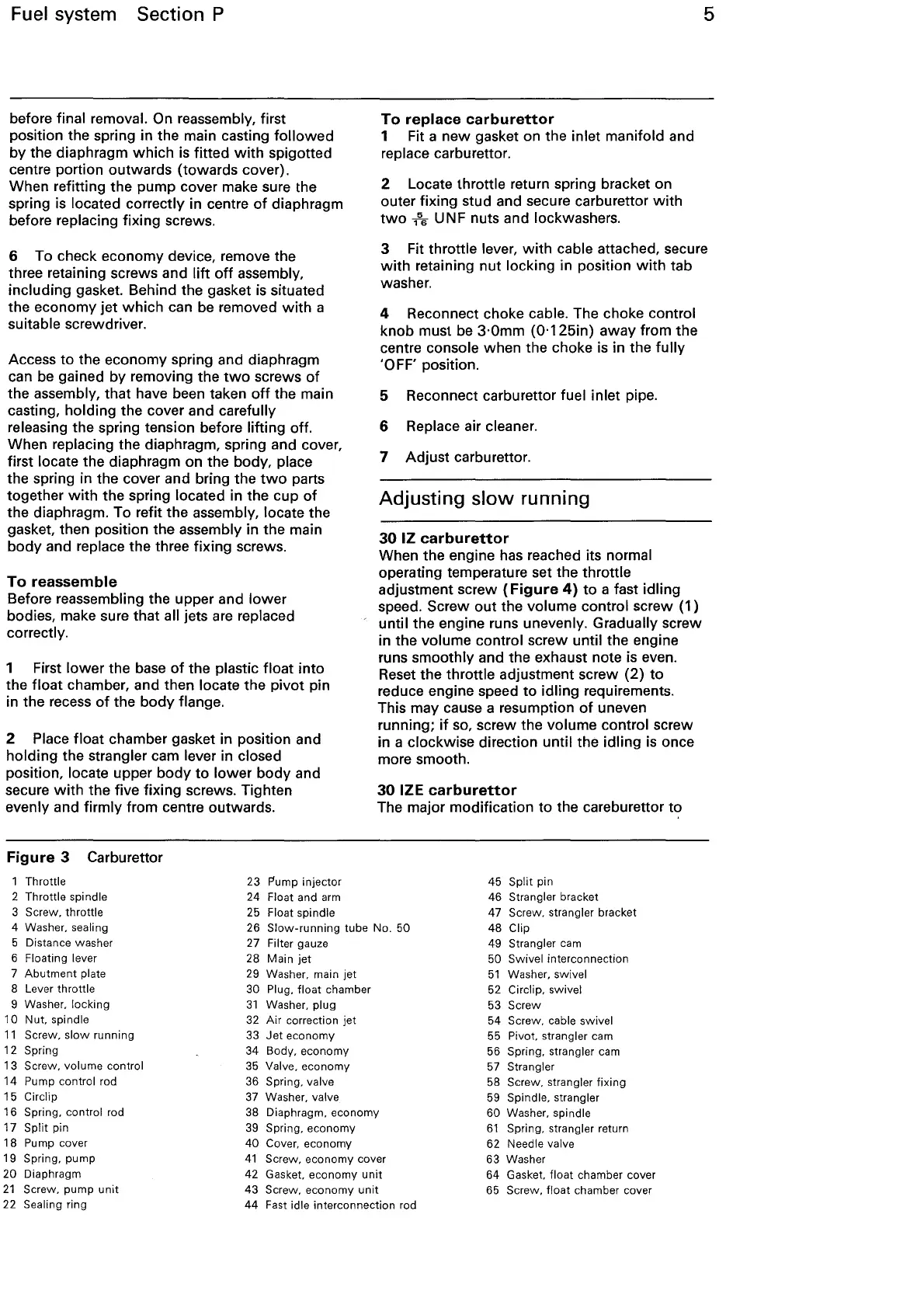
Figure
3 Carburettor
1 Throttle
2 Throttle spindle
3 Screw. throttle
23 Pump injector
24
Float and
arm
25 Float spindle
4 Reconnect choke cable. The choke control
knob must be
3·0mm
(0·125in)
away from
the
centre console when the choke is in the
fully
'OFF' position.
5 Reconnect carburettor fuel inlet pipe.
6 Replace air cleaner.
7
Adjust
carburettor.
Adjusting
slow
running
30
IZ
carburettor
When the engine has reached its normal
operating temperature set the throttle
adjustment screw
{Figure
4)
to
a fast idling
speed. Screw
out
the volume control screw {1)
until the engine runs unevenly.
Gradually screw
in the volume control screw until the engine
runs smoothly and the exhaust note is even.
Reset the throttle adjustment screw {2)
to
reduce engine speed
to
idling requirements.
This may cause a resumption
of
uneven
running;
if
so, screw the volume control screw
in a clockwise direction until the
idling
is once
more smooth.
30
IZE
carburettor
The major modification
to
the careburettor
t<:>
45 Split pin
46
Strangler bracket
4 Washer.
sealing
5 Distance washer
6
Floating lever
26
Slow-running
tube No. 50
27 Filter gauze
47
Screw. strangler bracket
48
Clip
49 Strangler
cam
7
Abutment
plate
8 Lever throttle
9 Washer. locking
10
Nut. spindle
11
Screw.
slow
running
12
Spring
13 Screw. volume control
14
Pump control rod
15 Circlip
16 Spring. control rod
17
Split pin
18 Pump cover
19
Spring. pump
20 Diaphragm
21
Screw. pump
unit
22 Sealing ring
28 Main jet
29
Washer. main jet
30 Plug.
float
chamber
31
Washer. plug
32
Air
correction
jet
33
Jet
economy
34 Body, economy
35
Valve. economy
36 Spring. valve
37
Washer. valve
38 Diaphragm. economy
39
Spring,economy
40
Cover. economy
41
Screw. economy cover
42 Gasket. economy
unit
43 Screw. economy
unit
44 Fast idle interconnection rod
50 Swivel interconnection
51
Washer. swivel
52 Circlip. swivel
53 Screw
54 Screw. cable swivel
55 Pivot. strangler cam
56
Spring. strangler
cam
57
Strangler
58 Screw. strangler fixing
59
Spindle. strangler
60
Washer. spindle
61
Spring, strangler return
62
Needle valve
63 Washer
64 Gasket.
float chamber cover
65 Screw. float chamber cover