The rear axle Section K
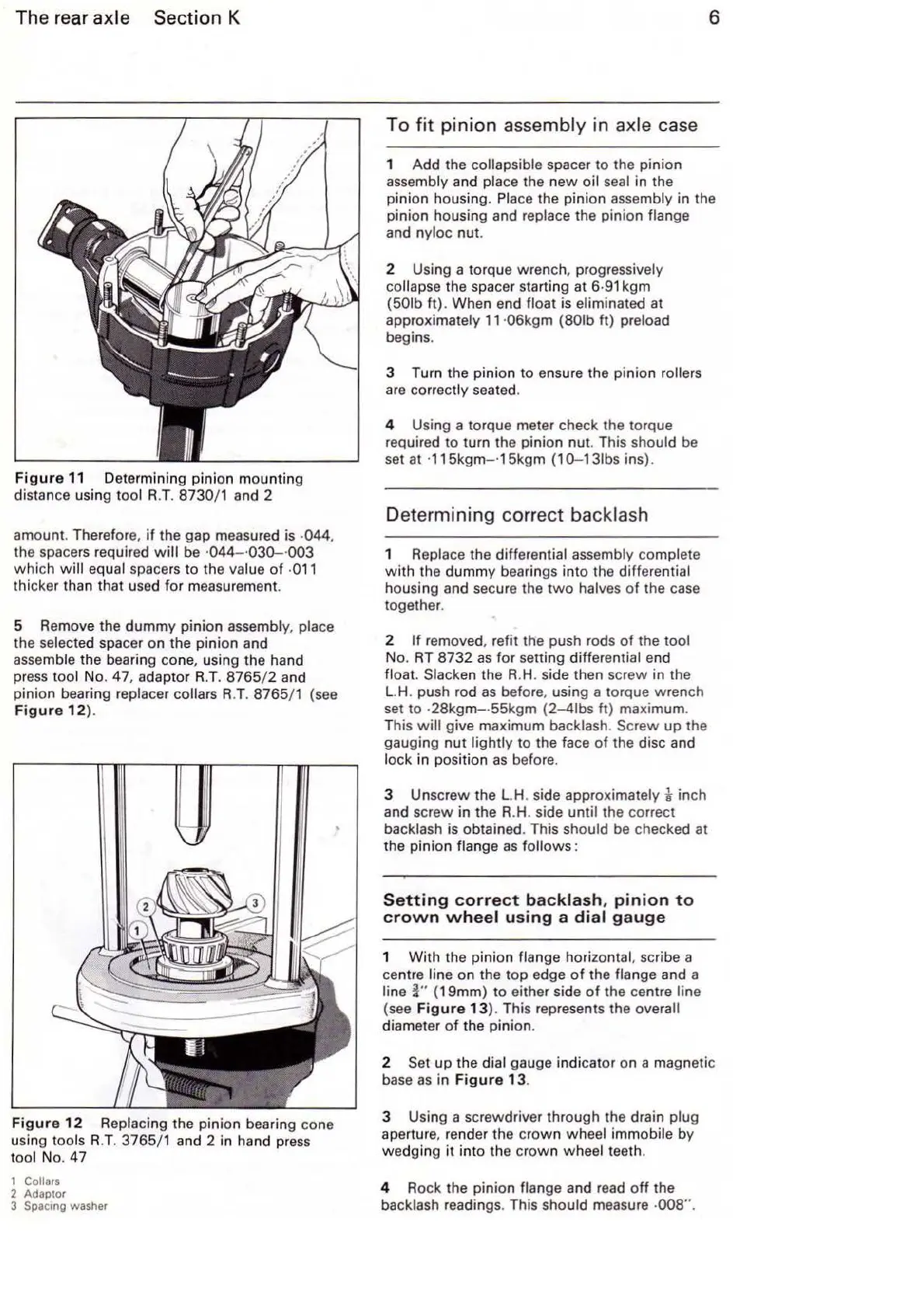
Figure
11
Determining pinion mounting
distance
us
ing tool R.
T.
8730/ 1 and 2
am
ount
. Therefore,
if
the gap measured is ·044.
the spacers required
will
be ·0
44-
·030
-·00
3
whi
ch
will
equal space
rs
to the value
of
·
011
thicker than that used for measurement.
5 Remove the dummy pinion
asse
mb
ly, place
the selected spacer on the pinion and
assemble the bearing co
ne
, using the hand
press
tool No. 47, adaptor
R.T.
8765
/ 2 and
pinion bearing replacer
collars R.T. 8765/1 (see
Figur
e
12
).
Figure
12
Replacing the pinion bearing cone
using
tools
R.T.
3765/1 and 2 in hand press
tool No. 47
1 Collars
2 Adaptor
3 Spacmg washer
6
To fit p
inio
n assembly in axle case
1 Add the collapsible spacer to the pinion
assembly
an
d place the new oil seal in the
pinion housing.
Pl
ace the pinion assembly in the
pinion housing and
replace the pinion flange
and nyloc nut.
2 Using a torque wrench, progressively
collapse the spacer starting
at
6·91
kgm
(501b
ft). When end float is eliminated at
approximately
11
·06kgm (801b ft) preload
begins.
3 Turn the pinion to ensure the pinion
rollers
are co
rr
ectly seated.
4 Using a torque meter check the torque
required to turn the pinion nut. This should
be
set at ·115kgm- ·15kgm
(1
0-131bs ins).
Determining correct backlash
1 Replace the differential assembly complete
with
the dummy bearings into the differential
housing and secure the
two
halves
of
the
case
together.
2
If
removed, refit the push rods
of
the tool
No.
RT
8732
as
for
setting differential end
float. Slacken the
R.H
. side then screw in the
L.H
. push rod
as
before, using a torque wrench
set to
·2
8kgm-
·55kgm (2-41bs ft) maximum.
This
will
give maximum backlash. Screw
up
the
gauging
nut
lightly to the face
of
the disc and
lock in position
as
before.
3 Unscrew the L.H. side approximately k inch
and screw in the R.H. side
until the correct
backlash is obtained. This
should be checked at
the pinion
flange
as
follows
:
Setting
correct
ba
ckl
ash
,
pinion
to
crown
wheel
using
a
dial
gauge
1
With
the pinion flange horizontal, scribe a
centre
line on the top edge
of
the flange and a
line
i"
(19mm) to either side
of
the centre line
(see
Figure
13). This represents the overall
diamet
er
of
the pinion.
2
Set
up
the dial gauge indicator on a magnetic
base
as
in
Figur
e
13
.
3 Using a screwdriver through the drain
plug
aperture, render the
crown
wheel immobile by
wedging
it
into the
crown
wheel teeth.
4 Rock the pinion
flange and read
off
the
backlash readings. This
should measure ·008".