Fuel system Section P
4 Slacken jubilee clip securing rubber tank
hose
to
filler tube.
5 Disconnect fuel supply pipe at sleeve
connector, located on
R.H
. chassis side member.
6 Remove nut and washer securing fuel tank
to
L.H
. and R.H. support straps.
7 Bend retaining straps outwards to clear tank
mounting studs. Take
ca
re
n
ot
to
damage the
mounting stud threads.
8
Carefully lower tank, disconnect
se
nder unit
lead, and remove fuel tank from
rear
of
vehicle.
9 Replace in rever
se
order.
Fuel tank sender unit
If
faulty readin
gs
are
suspected on the fuel
indicator check the indicator and sender unit
as
follows:
1
Rem
ove fuel tank
as
previously described.
2 Twist sender unit locking ring to r
elease
from tank location and w ithdr
aw
sender unit
(see
Figure
1
).
3 With sender unit lead still disconnected,
switch on vehicle ignition. The fuel indicator
needle should then
be
at the empty mark.
4
Earth
sender unit lead. The fuel indicator
needle should then
be
at the full mark, a
nd
this
will
confirm that the fuel indicator
is
functioning
correctly.
5 Reconnect sender unit lead and manually
operate the float
le
ve
r. With the float lever at
its bottom stop the
fuel indicator needle should
be
at the empty mark. With the float
le
ver at its
top
stop the fuel indicator
will
re
ad
full.
Any
deviation from these readings
will
confi
rm
that
the sender
unit
is faulty and will need replacing.
Fuel pump
Testing
the
fuel
pump
Providing there
are
no leaks or obstructions in
the fuel
line, a quick check on the fuel pump
efficien
cy
ca
n be made
as
follows:
1 Disconnect carburettor feed pipe at the
fuel pump
outlet.
2 Connect a slave pipe
to
the pump outlet
and place in a clean jar.
3
Crank the engine, when a well-defined
spurt
of
fuel should
be
apparent for
each
revolution
of
the engine.
If
the pump does not
operate
satisfactorily remove, dismantle and
fit
the necessary spare parts which
are
available
in a
repa
ir kit Part No. 11858.
To
remove
and
dismantle
(see
Figure
2)
2
1 Disconne
ct
fuel pump inlet and outlet pipes
and suitably
plug
to
prevent loss
of
fuel and
ingress
of
dirt.
2 Unscrew
two
nut
s,
complete
with
lockwashers and remove the pump by lifting
the operating lever
to
clear the camshaft
eccentric and the slotted aparture in the cylinder
block. Remove pump gasket.
3 Before dismantling clean the exterior
of
the
pump and mark the
base
of
the upper body in
line
with
the small diaphragm tab and mark
the
lower body, to ensure correct r
easse
mbl
y.
4 Remove fi
ve
screws and
sepa
rate the upper
and lower bodies
of
the pump.
5
Hold the pump in
an
in
verted position,
push
in
and then turn the diaphragm
asse
mbly
through
90
° to release the pull rod from the key
in the rocker arm extension. Remove diaphragm
assembly
an
d spring.
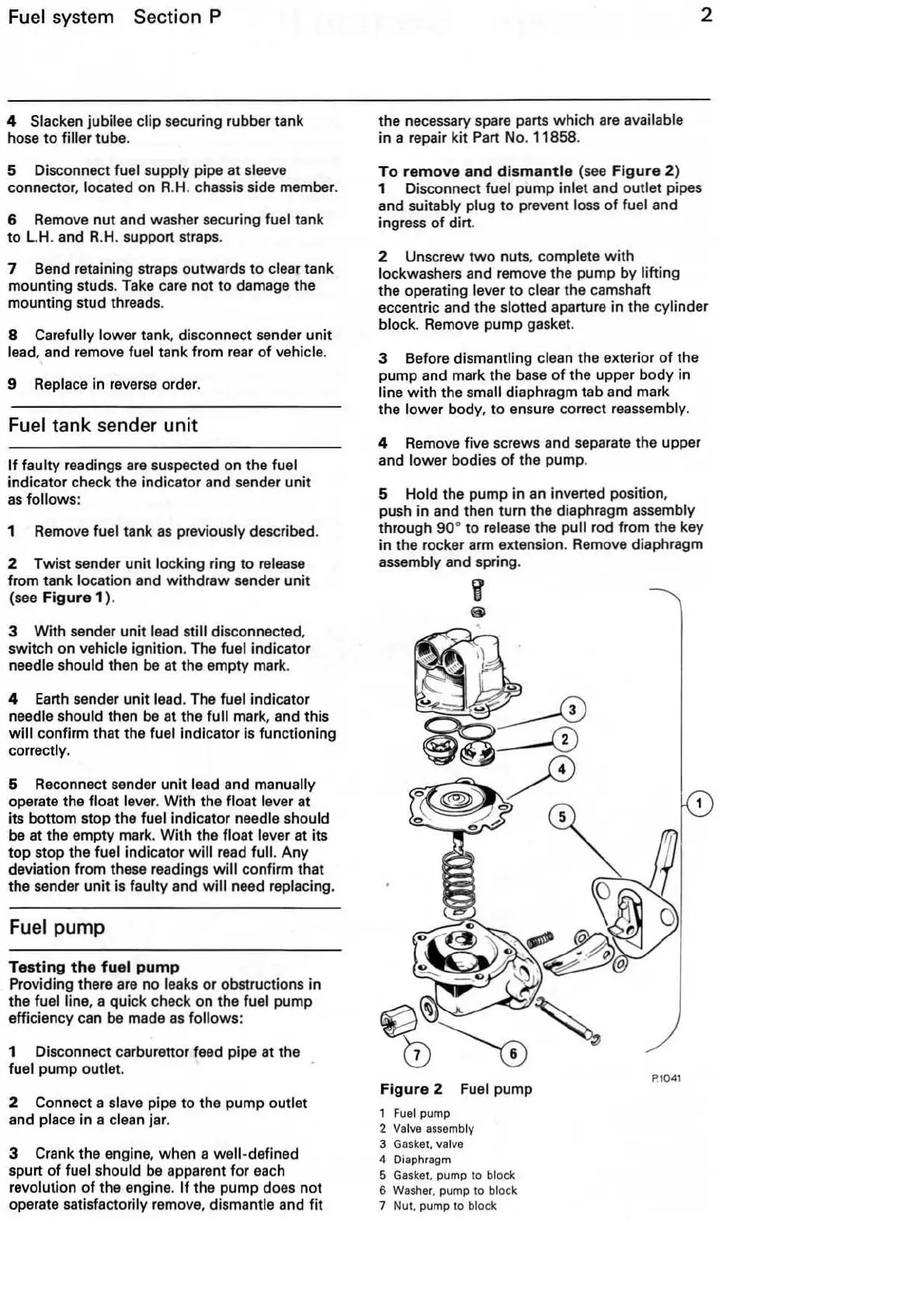
Figure
2 Fuel pump
1
Fuel
pump
2
Valve assembly
3
Gaske
t. valve
4 Diaphragm
5 Gasket. pump to block
6 Washer, pump to block
7 Nut. pump to block
1
P.10
41