Ele
ctri
cs
Section T
Igni
ti
on system
The ignition system comprises battery, ignition
sw
itch, coil, distributor and sparking plugs
as
shown in
Figur
e 1.
If
trouble is experienced
with
the ignition the
components shown in Figure 1
should be
systematically checked
to
diagnose the fault.
Particular
attention should be given to the
cleanlin
es
s and security
of
the earth braids.
for
if after inspecting the various electrical
components the ignition system still
fa
ils
to
function correctly, a loose braid could
be
the
cause.
The distributor is described in
full bel
ow
but
for
details
of
the other i
gnit
ion system components
refer
to
the General Electrics on page 18.
Distributor
D
esc
ripti
on
T
he
distributor is mounted on the
R.H
. side
of
the cylinder block and is driven by an offset
dog
from t
he
camshaft. Ignition advance is
mechanically controlled, according
to
engine
speed, by governor weights inside the distributor
body
. Distributor rotation is anti
-c
lockwise
viewed from above.
Lubri
c
ati
on
T
he
cam and contact breaker plate pivots and
bushin
gs,
whe
n assembling after overhaul.
sh
ould be lubricated
with
petroleum jelly. T
he
ca
m spi
nd
le governor weights and breaker arm
pivots
should
be
l
ub
ricated
with
engine oil every
3,000 miles (5,000km). To lubricate cam spindle
remove the rotor and apply
two
drops
of
oil
through the apertures in the breaker plate. Only
a film
of
engine oil should
be
applied to the
breaker arm pivot. ensuring that none
contaminates the distributor poin
ts
.
Caution: Do not over lubricate any part
of
the
distributor.
T
he
presence
of
dirt, oil
or
water on the
ignition
points, the central carbon brush,
or
on
the contact segments in the distributor
cover,
will
cause erratic running
or
may even prevent
the engine from running at
al
l.
Contact b
rea
ker po
int
s
To
a
dju
st
1 Remove the distributor cap and rotor arm.
2 Tu
rn
the engi
ne
so that the
hee
l
of
the
contact breaker is on the highest poi
nt
of
the
cam.
(It may
be
necessary to remove the
spa
rking plugs
to
eliminate the resistance caused
by compression.)
2
P1062
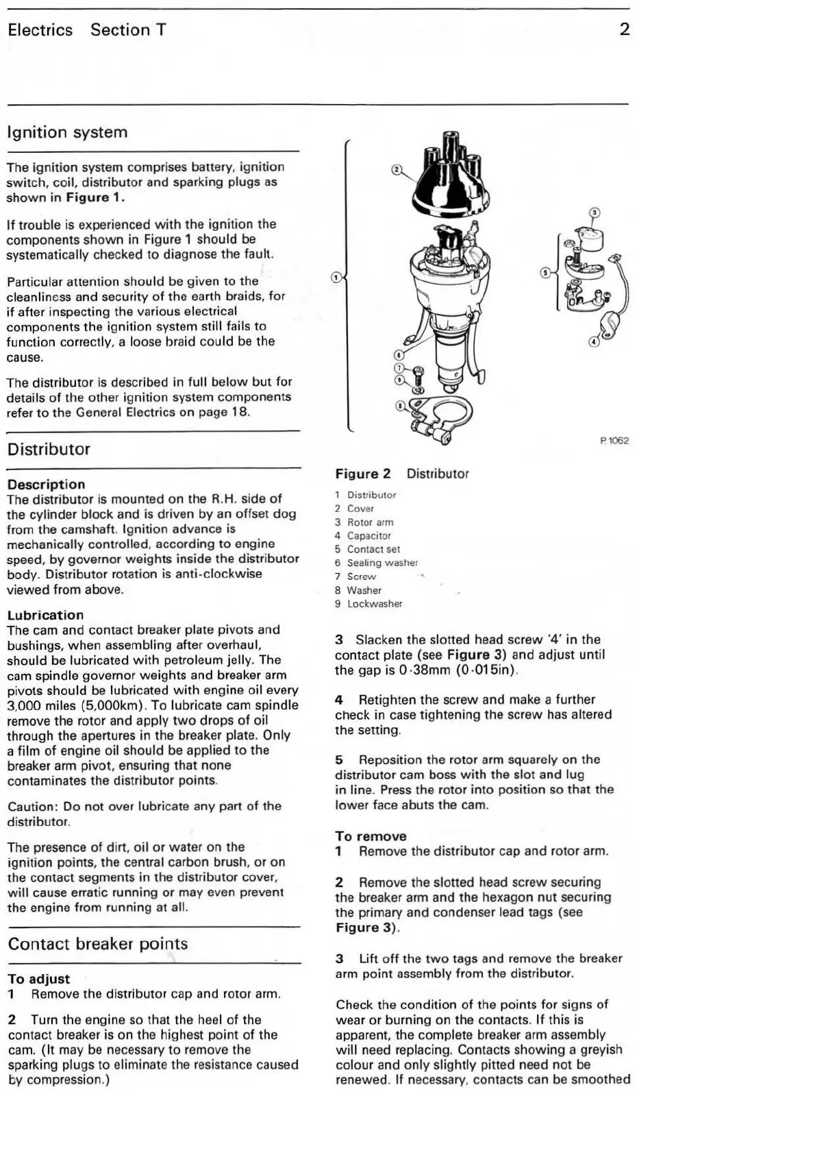
Fi
gur
e 2 Distributor
1 Distributor
2
Cover
3 Rotor arm
4 Capacitor
5
Contact set
6
Sealing washer
7
Screw
8 Washer
9 Lockwasher
3 Slacken the slotted head screw '4' in the
conta
ct
plate (see
Figur
e
3)
and adjust until
the gap is
0·38
mm (0 ·015in).
4 Retighten the scr
ew
and make a further
check in
case
tightening t
he
screw
has
altered
the setting.
5 Reposition the rotor arm
squarely on the
distributor cam boss
with
the sl
ot
and lug
in line.
Press
the rotor into position so that the
lower
face abuts the cam.
To
r
em
o
ve
1 Remove the distributor cap and rotor arm.
2 Remove the
slotted head screw securing
the breaker arm and the hexagon
nut
securing
the primary and condenser
lead tags (see
Figur
e
3)
.
3 Lift
off
the
two
tags and remove the breaker
arm point
assembly from the distributor.
Check the condition of the points
for
signs
of
wear
or
burning on the contacts. If this is
apparent. the
complete breaker arm assembly
will
need replacing. Contacts showing a greyish
colour and only slightly pitted need
not
be
renewed.
If
necessary, contacts can
be
smoothed