The
brakes
Section L
1
Description
The braking system employs
two
leading shoes
on the front
wheel, hydraulica
ll
y operated. The
rear brakes. also hydraulic, use a leading and
trailing shoe. A mechanical handbrake linkage is
provided
to
the rear brakes only.
The br
ake
pedal, connected directly to the
master cylinder via short push
r
od
, also
operates a stop
light switch mounted on the
pedal bracket assembly.
Routine ma
int
enance and adjustment
Check the level
of
the brake master cylinder
fluid weekly and top up if necessary. Every
3,000 miles
(5
,000km)check and adjust brakes
and hydraulic system, and grease hand brake
cable.
Front brake adjustment
A manual eccentric pin type adjuster is fitted
to both brake shoes (see
Figure
1 ).
1 Check that the brake drums
are
cold
.
2 Jack up the vehicle
until front wheel is
clear
of
the ground.
3 Turn the adjuster
of
one shoe anti-clockwise
to
bring the lining away from the drum. Turn
the other adjuster until the drum is
locked, then
slacken back
until the wheel is just sufficiently
free
to
rotate
without
binding.
4 Turn the other adjuster until the drum is
locked. then slacken back until the wheel is
aga
in sufficiently free
to
rotate
without
binding.
Figure
1 Front brake adjustment
1 Gr
ease
nipple
2 Bleed screw
3 Adju
ste
r
N
ote:
This adjustment
mu
st be performed
accurately
to
obtain a minimum clearance
between the linings and the drum.
with
consequent minimum pedal travel.
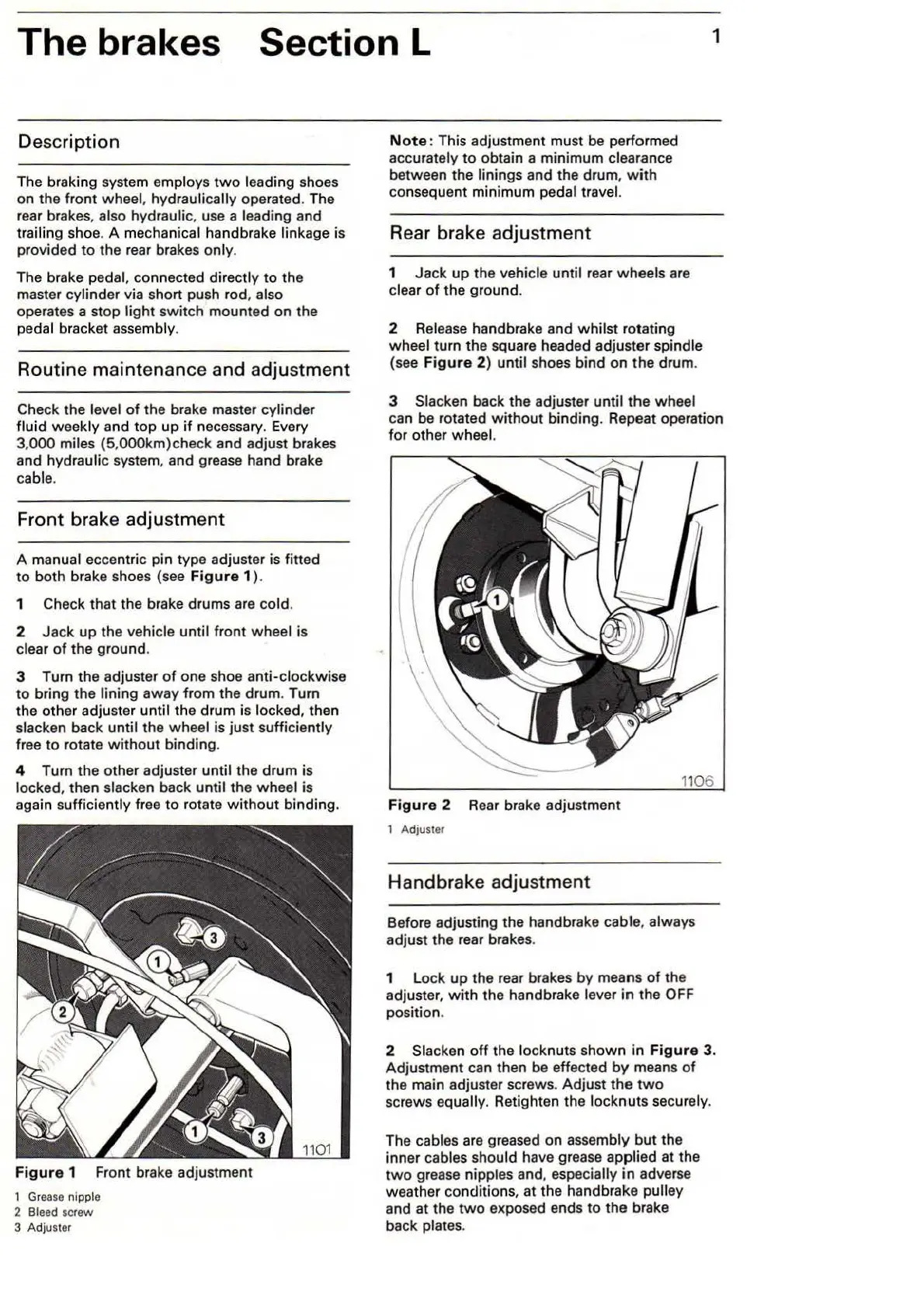
Rear brake adjustment
1 Jack
up
the vehicle until rear wheels are
clear
of
the ground.
2 Release handbrake and whilst rotating
wheel
tur
n the square headed adjuster spindle
(see
Figure
2) until shoes bind on
the
drum.
3 Slacken back the adjuster
until the wheel
can be rotated
without
binding. Repeat operation
for other wh
ee
l.
Fi
gure
2
Rear
brake adjustment
1 Adjuster
Handbrake
ad
ju
stment
Before adjusting the handbrake cab'le, always
adjust the rear brakes.
1 Lock
up
the rear brakes by means
of
the
adjuster, with the handbrake lever
in
the OFF
position.
2 Slacken
off
the
lo
ck
nut
s shown
in
Figure
3.
Adjustment can then be effected
by
means
of
the main adjuster screws. Adjust
the
two
screws equally. Retighten the locknuts securely.
The cables are greased on assembly
but
the
inner cables should have grease applied at the
two
grease nipples and, especially
in
adver
se
weather condition
s,
at the handbrake pulley
and at the
two
exposed ends to the brake
back plates.