The body Section 0
7 Replace
in
reverse
order. After fitting the
external handle to the door. the plunger screw
(adjuster
sc
r
ew)
should be adjusted
to
give a
clearan
ce
of
1 ·58mm (0·063in) between the
plunger and
lo
ck thrust plate.
Adjustment
of
door
striker plate
3 Retighten striker plate retaining screws and
then check that door
lock mechanism makes a
good
seating on the catch.
Window
frame and gla
ss
To
remov
e (see
Figure
2)
2
1 Slacken the
two
striker plate retaining
screws. DO NOT remove the screws. otherwise
the catch
of
the striker plate
wi
ll fall between
the inn
er
and outer body.
1 Remove
door
casing. regulator mechanism
and door lock mechanism.
as
previously described.
2 Remove the waterproof sheet completely
from the door.
2 Adjust the striker plate (elo
nga
ted holes in
th
e body facilitate this) until the door is flush
with
the body.
3 With the
window
fully closed prise the silent
channel from the bottom
of
the
window
frame
to
gain
access
to
the lower frame retaining
rivets.
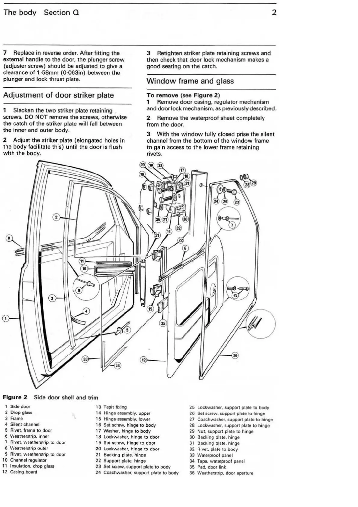
Figure 2 Side door shell and trim
1 Side door
2 Drop
glass
3
Frame
4 Silent channel
5 Rivet.
frame
to door
6 Weatherstrip,
Inner
7 Rivet. weatherstrip to door
8 Weatherstrip outer
9 Rivet. weatherstrip to door
10 Channel regulator
11
Insulation. drop glass
12
Cas
ing board
13 Tapit
fming
14
Hinge assembly, upper
15 Hingo
assembly, lower
16
Set
scre
w. hinge to body
17
Washer
. hinge to body
18
Lo
ckwasher. hinge to door
1 9
Set
screw. hinge to door
20 Lockwash
er.
hinge to door
21
Backing plate. hinge
22
Support plate. hinge
23
Set screw. support plate to body
24 Coachwasher. support plate to body
25 Lockwasher. support plate to body
26
Set
screw. support plate to hinge
27 Coachwasher. support plate to hinge
28
Lockwasher. support plate to hinge
29
Nut. support plate to hingo
30
Ba
cking pl
ate.
hinge
31
Ba
cking plate. hi
ng
e
32 Rivet. plate to body
33 Waterproof
panel
34
Tape.
waterproof panel
35
Pad.
door link
36 Weatherstnp. door aperture