Electrics Section T
Starting system
The starting system comprises battery, ignition
switch, solenoid and starter motor,
as
shown
in
Figure
5.
If
the starter fails
to
operate when the ignition
is switched
on
the components in
Figure
5
should
be
systematically checked to diagnose
the fault. Examine the starter pinion which may
be jamming
in
mesh
with
the flywheel ring gear.
It
can be released by turning the squared end
of
the pinion shaft in
an
anti-clockwise direction.
Check that the battery is
in
a good state
of
charge and the terminals free from corrosion.
The condition and security
of
the earth braids
is also important. The starter solenoid could also
be at fault. When the ignition is switched on the
starter motor pinion makes a distinct sound
when meshing
with
the flywheel ring gear and
if
this is
not
apparent, a faulty solenoid could
be indicated.
If
the components
of
the starting system are
found to be functioning cor
re
ctly this would
indicate that the fault lies in the ignition or
charging systems (see
Figure
1 and
Figure
7).
The starter motor and testing procedure is
described below
but
for details
of
the other
starting system components refer to the General
Electrics on page
18
.
Starter
motor
Description
The
starte~
motor is a
fou
r pole, four brush
machine
with
inertia drive and is
se
cured in the
R.H
. side to the rear engine plate and gearbox
bell housing.
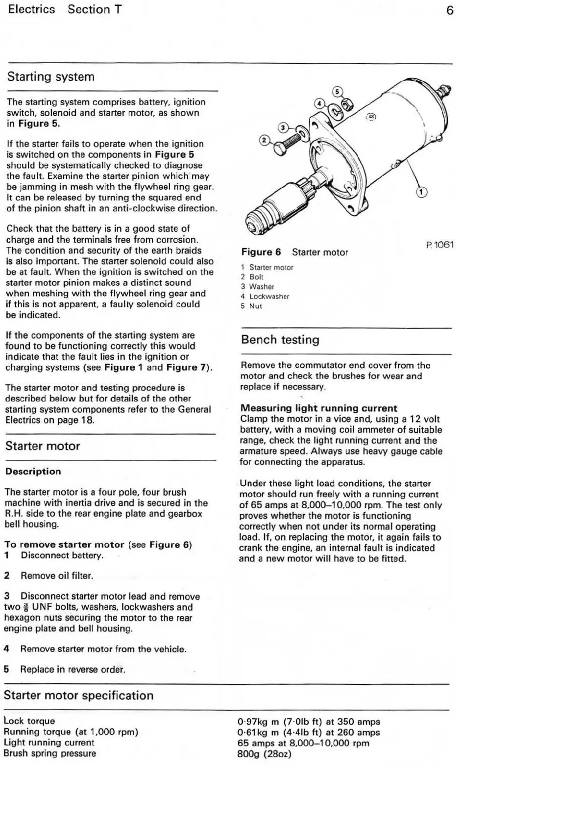
To
remove
starter
motor
(see
Figure
6)
1 Disconnect battery.
2 Remove oil
filter.
3 Disconnect starter motor lead and remo
ve
two
i UN F bolts, washers, lockwashers and
hexagon nuts securing the motor
to
the rear
engine plate and
bell housing.
4 Remove starter motor from the vehicle.
5 Replace
in
reverse order.
Starter
motor
specification
lo
ck torque
Running torque (at
1,000 rpm)
ligh
t running current
Brush spring pressure
6
Figure
6 Starter motor
P.
1
061
1 Starter motor
2
Bolt
3 Washer
4 Lockwasher
5
Nut
Bench testing
Remove the commutator end cover from the
motor and check the brushes for wear and
replace
if
necessary.
Measuring
light
running
current
Clamp the motor in a vice and, using a
12
volt
battery, with a moving coil ammeter
of
suitable
range, check the li
ght
running current and the
armature speed. Always use heavy gauge cable
for connecting the apparatus.
Under these light load condition
s,
the starter
motor should run freely
with
a running current
of
65
amps at 8,000-1 0,
000
rpm. The test
only
proves whether the motor is functioning
correctly when not under
its
normal operating
load.
If
, on replacing the motor, it again fails
to
crank the engine,
an
int
ernal fault is indicated
and a new motor
will
have
to
be fitted.
0·97kg m (7·01b
ft)
at 350 amps
0·
61
kg m (4·41b ft) at 260 amps
65 amps at
8,
000-10
,
000
rpm
800g (28oz)