The brakes Section L
Figur
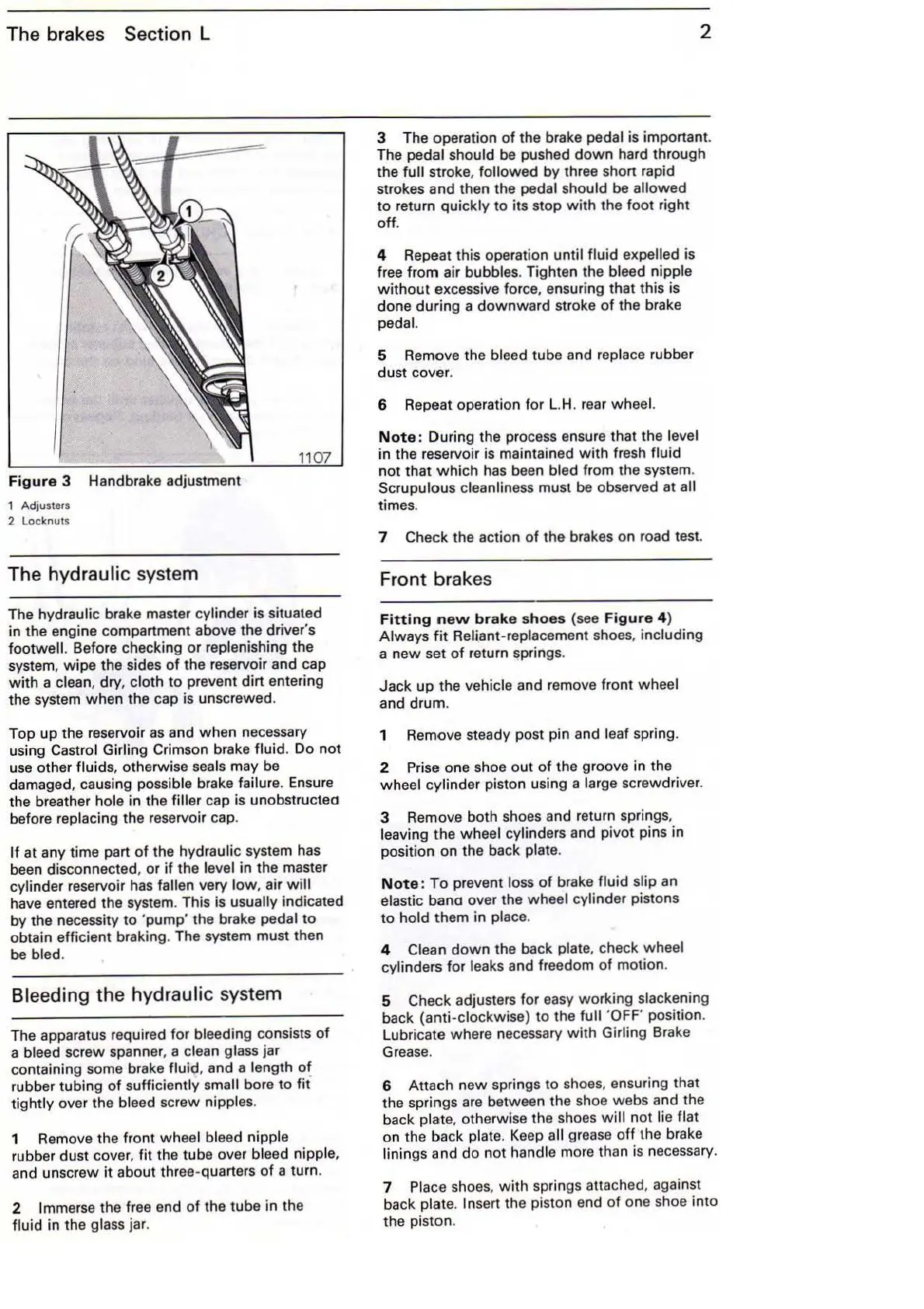
e 3 Handbrake adjustment
1 Adjusters
2 Locknuts
The hydraulic system
The hydraulic brake master cylinder is s
itu
ated
in
the engine compartment above the driver's
footwall. Before checking
or
replenishi
ng
the
system,
wipe
the sides
of
the reserv
oi
r and cap
with
a clean, dry, cloth
to
prevent dirt entering
the system
when
the cap is unscrewed.
Top
up
the reservoir
as
and
when
necessary
using Castro! Girling Crimson brake
fluid
. Do
not
use other fluids, otherwi
se
seals may be
damaged, causing possible brake
failure. Ensure
the breather
hole in the filler cap is unobstructea
before replacing the reservoir cap.
If at any time part
of
the hydraulic system has
been disconnected, or
if
the level in the master
cylinder reservoir has
fallen very
low
, air
will
have entered the system. This is usually indicated
by the necessity to 'pump' the brake pedal
to
obtain efficient braking. The system must then
be bled.
Bleeding the hydraulic system
The apparatus required
for
bleeding consists
of
a bleed screw spanner, a clean glass jar
containing some brake
flu
id
, and a length
of
rubber tubing
of
sufficiently small bore to
fit
tightly
over the bleed screw nippl
es.
1 Remove the front wheel bleed nipple
rubber dust cover, fit the tube over bleed nipple,
and unscrew
it
about three-quarters
of
a turn.
2 Immerse the fr
ee
end
of
the tube in the
fluid in the glass j
ar
.
2
3 The operation
of
the brake pedal is important.
The pedal should
be
pushed
down
hard through
the
full stroke, followed by thr
ee
short
ra
pid
strokes and then the pedal should be
allowed
to
return quickly to its stop
with
the
foot
right
off
.
4 Repeat this operation
until fluid expelled is
free from air
bubb
les. Tighten the bleed nipple
without
excessive force, ensuring that this is
done
during
a
downward
stroke of the brake
pedal.
5 Remove the bleed tube and replace rubber
dust cover.
6 Repeat operation for L.H.
re
ar
wheel.
Note
: During the process ensure that the level
in the reservoir is maintained
with
fresh fluid
not
that
which
has been bled from the system.
Scrupulous cleanlin
ess
must
be
observed at all
times.
7 Check the action
of
the brakes on road test.
Front brakes
Fitting
new
brake
s
ho
es (see
Figure
4)
Always
fit
Reliant-replacement shoes, including
a
new
set
of
return springs.
Jack
up
the vehicle and remove front wheel
and
drum
.
1 Remove steady post pin and
leaf spring.
2 Prise one shoe
out
of
the groove in the
wheel cylinder piston using a large screwdriver.
3
Remov.e
both shoes and return springs,
leaving the wheel cylinders a
nd
pivot pins in
position on the back plate.
Note
:
To
prevent loss
of
brake fluid slip an
elastic bana over the wheel cylinder pistons
to
ho
ld them in place.
4 Clean
down
the back plate, check wheel
cylinders for leaks and freedom
of
motion.
5 Check adjusters for easy working slackening
back (anti-clockwise) to the
full 'OFF' position.
Lubricate where necessary
with
Girling Brake
Grease.
6 Attach new springs
to
shoes, ensuring that
the springs are between the shoe webs and the
back
plate, otherwise the shoes
will
not
lie flat
on the back plate.
Keep
all grease
off
the brake
linings and do
not
handle more than
is
ne
cessary.
7
Pla
ce shoes,
with
springs attached, against
back plate.
Insert the piston end
of
one shoe
into
the piston.