Fuel system
Section P
1
Description
Fuel is delivered
to
the carburettor by a
camshaft operated diaphragm pump from a
rectangular fuel tank mounted under the floor at
the rear
of
the vehicle. The fuel is filtered by a
gauze filter located on the pick-up pipe
of
the
sender unit
in
the tank. The float operated
sender unit actuates the fuel gauge on the
fascia.
A downdraught carburettor is used incorporating
a diaphragm accelerating pump and a
depression operated economy device.
Vehicles built after September 1973,
will
have
a carburettor that conforms
with
the Department
of
Environment Vehicle Emmission Regulations.
Early vehicles have identical carburettors
with
the exception
of
modifications made by the
manufacturer
to
conform
with
the Regulations.
The carburettor is a
30
IZ or
30
IZE model, the
latter being the emission controlled type.
Air
is filtered through the carburettor by a
dry
paper element type air cleaner that also serves
the engine oil
filler cap.
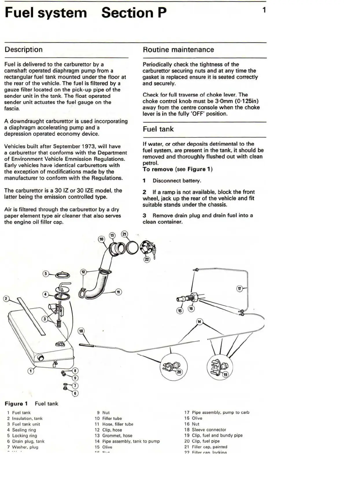
F
igure
1 Fuel tank
1
Fuel
tank
2 Insulation. tank
3
Fue
l tank unit
4
Sea
ling ring
5 Locking ring
9 Nut
10 Filler tube
11
H
ose.
filler tube
12
Clip. hose
13
Grommet. hose
Routine maintenance
Periodically check the tightness
of
the
carburettor securing nuts and at any time the
gasket is replaced ensure it is seated correctly
and securely.
Check
for
full
traverse
of
choke lever. The
choke control knob must
be 3·0mm
(0
·125in)
away from the centre console when the choke
l
eve
r is in the fully
'OFF
position.
Fuel tank
If water, or other deposits detrimental
to
the
fuel system, are present in the tank.
it
should be
removed and thoroughly flushed out
with
clean
petrol.
To r
emo
ve (see
Fig
ur
e
1)
1 Disconnect battery.
2
If
a ramp is
not
available, block the front
wheel, jack up the rear
of
the vehicle and fit
suitable stands under the chassis.
3 Remove drain plug and drain fuel into a
clean container.
17
Pipe
assembly. pump to carb
15 Olive
16
Nut
18
Sleeve connector
6 Drain
plug. tank
7 Washer.
pl
ug
14
Pipe
assembly. tank to pump
15 Olive
19
Clip. fuel and bundy pipe
20 Clip. fuel pipe
21
Filler cap. painted
? ?
l"ill<>r
N>n
ln~kinn