Electrics Section T
Figure
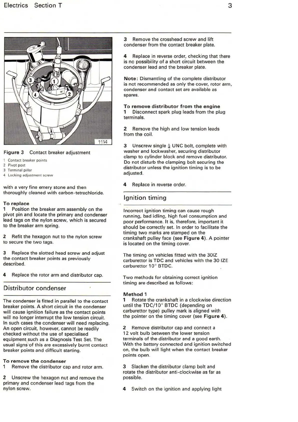
3 Contact breaker adjustment
1 Contact breaker points
2 Pivot post
3
Terminal pillar
4 Locking adjustment screw
with
a very fine emery stone and then
thoroughly
cleaned with carbon-tetrachloride.
To
replace
1 Posi
ti
on the breaker arm assembly on the
piv
ot
pin and locate the primary and conden
se
r
lead tags on the n
ylo
n screw,
which
is secured
to the breaker arm spring.
2 Refit the hexagon nut
to
the
ny
lon screw
to
secure the
two
tags.
3 Replace the slotted head screw and adjust
the contact breaker points
as
previously
described.
4
Replace the rotor arm and distributor cap.
Distributor condenser
The condenser is fitted in parallel to the contact
br
eaker points. A short circ
uit
in the condenser
will
cause ignition failure
as
the contact points
will
no
longer interrupt the
low
tension circuit.
In such cases the condenser
will
need replacing.
An open
circui
t,
however, cann
ot
be
readily
checked w
it
hout the use
of
specialised
equipment such
as
a Diagnosis Test Set. The
usual signs
of
this
are
excessively burnt contact
breaker po
int
s and
difficult
starting.
To
remove
the
condenser
1 Remove the distributor cap and rotor ar
m.
2 Unscrew the hexagon
nut
and remove the
primary and condenser
lead tags from the
nylon screw.
3 Remove the crosshead screw and
lift
co
ndenser from the contact breaker plate.
3
4 Replace in reverse order, checking that there
is
no
possibility
of
a short circuit between the
condenser
l
ea
d and the breaker plate.
Not
e:
Dismantling
of
the complete distributor
is
not
recommended
as
only the cover, rotor arm,
condenser and contact set
are
available
as
spares.
To
remove
distributor
from
the
engine
1 Disconnect spark plug leads from the plug
terminals.
2 Remove the high and
low
tension leads
from the coil.
3 Unscrew single i UNC
bolt
, complete with
washer and
lockwasher, securing distr
ib
utor
clamp
to
cylinder block and remove distributor.
Do not disturb the clamping
bolt
securing the
distributor
un
less the ignition timing is to be
adjusted.
4
Rep
lace in reverse ord
er.
Ignition
timing
Incorrect ignition timing
ca
n cause rough
running, bad
idling, high fuel consumption and
poor performance.
It
is, therefore, important
it
should be correctly set. In order to facilitate the
timing
two
marks
are
stamped on the
crankshaft
pulley face (see
Figure
4). A pointer
is
located on the timing cover.
The timing on vehicles fitted w ith the
301Z
carburettor is TDC and vehicles
with
the
30
IZE
carburettor
10
° BTDC.
Two
methods for obtaining correct ignition
timing are described
as
follows
:
Method
1
1 Rotate the crankshaft in a clockwise direction
until
the
TDC/1 0° BTDC (depending on
carburettor type)
pulley mark is aligned
with
the pointer on the timing cover (see
Figure
4).
2 Remove distributor cap and connect a
12
volt
bulb between the
lower
tension
terminals
of
the distributor and a
good
earth.
With
the battery connected and i
gnit
ion switched
on, t
he
bulb will light when the contact breaker
points open.
3
Slacken the distributor clamp
bolt
and
rotate the distributor anti-clockwise
as
fa
r
as
possible.
4
Switch
on the ignition and applying light