The engine Section F
19
Remove plug and connect petrol supply
pipe at fuel pump.
20
Reconnect choke cable at carburettor and
throttle cable at pedal.
21
Refit air cleaner.
22
Reconnect coil high and
low
tension leads.
23
Reconnect oil pressure indicator lead at
cylinder block.
24
Reconnect temperature gauge sender unit
lead at thermostat housing.
25
Reconnect starter motor lead.
26
Refit alternator and connect leads.
27 Refill engine and gearbox
with
recommended oil.
28
Refill the cooling system.
29 Reconnect battery.
Operation
2-
Flywheel and ring
gear
removal and replacement
1 Remove gearbox (see Section G - The
Gearbox).
2 Unscrew six set screws,
complete
with
lockwashers, and remove clutch assembly from
the
flywheel.
3 Release tab washer, unscrew three set
screws and remove
flywheel assembly from the
crankshaft.
4
Drill or cut ring gear and prise from flywheel.
5 Heat
new
ring gear evenly and
fit
to
flywheel.
6 Using a 0·038mm (0·0015in) feeler gauge
check that no
clearance exists between ring
gear and
flywheel over the complete
circumference.
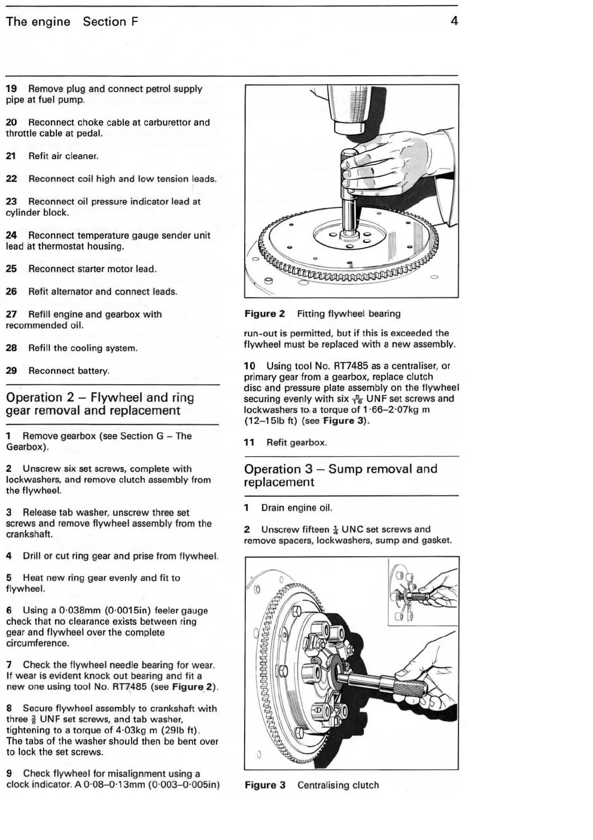
7 Check the
flywheel needle bearing for wear.
If wear is evident knock
out
bearing and fit a
new one using
tool No. RT7485 (see
Figure
2).
8
Secure flywheel assembly
to
crankshaft
with
three i UNF set screws, and tab washer,
tightening
to
a torque
of
4·03kg m
(291b
ft).
The tabs
of
the washer should then be bent over
to
lock the set screws.
9 Check
flywheel for misalignment using a
clock indicator. A 0·
08-0·13mm
(0·
003-0
·005in)
4
Figure
2 Fitting flywheel bearing
run-out is permitted,
but
if
this is exceeded the
flywheel must be replaced
with
a new assembly.
10
Using tool No. RT7485
as
a centrali
ser,
or
primary gear from a gearbox,
replace clutch
disc and pressure plate assembly on the flywheel
securing evenly
with
six
1
5
6
UNF set screws and
lockwashers
to
a torque
of
1·66-2
·07kg m
(12-151b
ft)
(see
Figure
3)
.
11 Refit gearbox.
Operation 3 - Sump removal and
replacement
1 Drain engine oil.
2 Unscrew fifteen 1
UNC
set screws and
remove spacers,
lockwashers, sump and gasket.
Figure
3 Centralising clutch