The brakes Section L
Figure
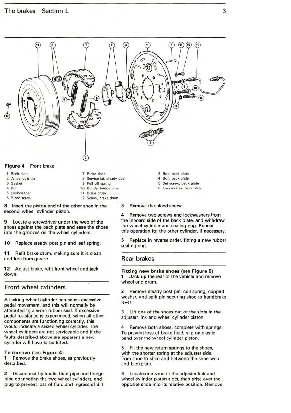
4 Front brake
1
Bac
k plate
3
7
Bra
ke shoe
2
Wheel cylinder
3 Gasket
8
Serv
ice
ki
t. st
ea
dy
post
9
Pu
ll
off
spring
13
Bolt. back plate
14 Bolt. back plate
1 5
Se
t screw. back plate
16
Lockwasher. back plate 4 Bolt
5 Lo
ckw
asher
6
Bleed scr
ew
1 0 Bundy. bridge pipe
11
Brake drum
12 Screw. br
ake
drum
8 Insert the piston end
of
the other shoe
in
the
second wheel cylinder piston.
9 Locate a screwdriver under the
web
of
the
shoes against the back plate and ease the shoes
into
the grooves on the wheel
cy
linders.
1
0 Replace steady post pin and leaf sprin
g.
11 Refit brake drum, making sure
it
is clean
and free from grease.
12
Adjust brake, refit front wheel and jack
down.
Front wheel
cy
linders
A leaking wheel cylinder can cause excessive
pedal movement, and this
will
normally
be
attributed
t
~
a worn rubber seal.
If
excessive
pedal
res
istance is experienced, when all other
components are functioning correctl
y,
this
would
indicate a seized wheel cylinder. The
wheel cylinders are not serviceable and
if
the
faults described above
are
apparent a new
cylinder
will
have to
be
fitted.
To
remove
(see
Figur
e 4)
1 Remove the brake shoes,
as
previously
described.
2 Disconnect hydraulic fluid pipe and bridge
pipe connecting the
two
wheel cylinders, and
plug
to
prevent loss
of
fluid
and ingress of dirt.
3 Remove the bleed screw.
4 Remove
two
screws and lockwashers from
the inboard side
of
the back plate, and
with
dr
aw
the wheel
cy
linder and sealing ring. Repeat
this operation
for
the other cylinder,
if
necessary.
5 Replace in
re
verse order, fitting a n
ew
rubber
sealing ring.
R
ea
r brak
es
F
itt
ing
new
brak
e
shoes
(see
Figure
5)
1 Jack
up
the rear
of
the vehicle and remove
wheel and drum.
2 Remove steady post pin, coil spring, cupped
washer, and split pin securing shoe
to
handbrake
lever.
3 Lift one
of
the shoes
out
of
the slots in the
adjuster link and wheel cylinder piston.
4 Remove both shoes, complete
with
springs.
To prevent loss
of
brake
fluid
, slip on elastic
band over the wheel cylinder piston.
5 Fit the new return springs to the shoes,
with
the shorter spring at the adjuster side,
from shoe
to
shoe and between the shoe
web
and backplate.
6 Locate one shoe in the adjuster link and
wheel cylinder piston
slots, then pri
se
over the
opposite shoe into its relative position. Remove