The brakes Section L
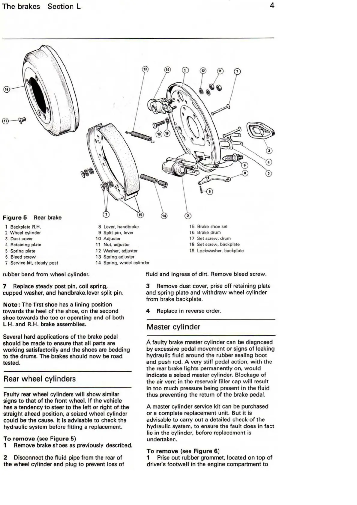
Figure
5 R
ea
r brake
1 Backplate
R.H
.
2 Wheel cylinder
3
Oust cover
4 Retaining plate
5
Spring plate
6 Bleed screw
8 Lever. handbrake
9 Split pin. lever
10
Adjuster
11
Nut. adjuster
12 Washer. adjuster
13 Spring adjuster
15 Brake shoe set
16
Brake
drum
17
Set screw. drum
18 Set screw. backplate
19 Lockwasher. backplate
4
7 Service kit. steady post
14 Spring. wheel cylinder
rubber band from wheel cylinder.
7 Replace steady post pin.
coil spring,
cupped washer, and handbrake.lever
sp
lit pin.
Note:
The
fir
st shoe
has
a lining position
towards the heel
of
the shoe, on the second
shoe towards the toe or operating end of both
L.H.
and R.H. brake
asse
mbli
es.
Several hard applications
of
the brake pedal
should
be
made
to
ensure that all parts
are
working satisfactorily and the shoes
are
bedding
to
the drums. The
bra
kes
sho
ul
d n
ow
be
road
te
ste
d.
Rear
wheel cylinders
Faulty rear wheel cylind
ers
will
show similar
signs
to
that
of
the front wheel.
If
the
ve
hi
c
le
has
a tendency
to
steer
to
the left or right
of
.the
straight ahead position, a seized wheel cylinder
could
be
the
ca
u
se.
It
is advisable
to
check the
hydraulic system before fitting a replacement.
To
remove
(
see
Figure
5)
1 Remove brake shoes
as
previously described.
2 Disconnect the fluid pipe from the r
ea
r
of
the wheel cylinder and plug
to
prevent lo
ss
of
fluid and ingress
of
dirt.
Re
move bleed
sc
rew.
3 Remove dust
cover, pr
ise
off
retaining plate
and spring plate and withdraw wheel cylinder
from brake backplate.
4
Repl
ace
in reve
rse
order.
Master cylinder
A faul
ty
brake master cylinder can
be
diagnosed
by excessive
pedal movement or signs of leaking
hydraulic
fluid around the rubber sealing boot
and push rod. A very stiff
pedal action.
with
the
the
rea
r brake lights permanently on,
would
in
dicate a seized master cylinder. Blockage
of
the air vent in
the
reservoir filler cap
will
result
in too much pressure being present in the
fluid
thus preventing the return
of
the brake pedal.
A
ma
ster cylinder service kit can
be
purchased
or a complete replacement unit. But
it
is
advisable
to
ca
rry
out
a detailed check
of
the
hydraulic system. to ensure the
fault does
in
fact
lie in the cylinder. before replacement
is
undertak
en.
To
remove
(see
Figure
6)
1 Prise
out
rubber grommet, located on top
of
driver's footwall in the engine compartment
to