The rear axle Section K
4 Disconnect flexible brake hose from bundy
tube at rear
axle, and plug
to
prevent loss
of
fluid and ingress
of
dirt
.
5
Supporting the axle, remove both damper
fixing
bolts from the axle mountin
gs.
6 Unscrew four nuts and locknuts and remove
the
two
'U'
bolts securing the le
af
springs to
axle. The axle
unit
can
now
be removed from
the
vehicle.
To replace axle unit
1 Carefully raise the axle and seat on the
location pegs
of
the leaf springs.
2
Secure axle to leaf springs
with
·u
· bolts
and i UNF nuts and lockwashers.
3 Fit damper units to
axle mounting
with
i UNF nuts and bolts.
4 Reconnect flexible brake hose to bundy tube
at
axle mounting.
5 Reconnect handbrake
cable clevises to
brake
levers
with
clevis pin and washer and
new
split pin.
6
Replace drive shaft.
7 Ref
it
road wheels and
if
applicable, remove
stands and jack
down
the vehicle.
8 Bleed the brakes (see
Section
L).
To fit
new
halfshaft
bea
rin
gs-
with axle in vehicle
1
If
a ramp is
not
available, jack
up
the rear
of
the vehicle, place suitable stands under the
chassis and remove road
wheels.
2 Disconnect hydraulic brake pipes at brake
backplate.
3
Slacken brake adjusters, remove the one
countersunk screw and
lever
off
the R.H. brake
drum.
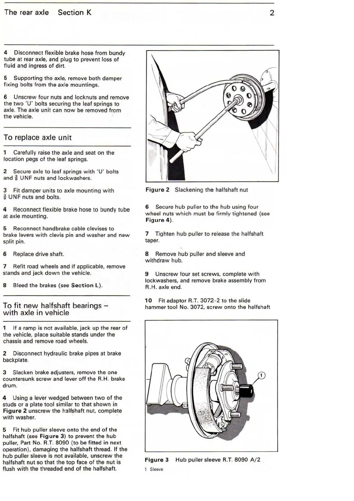
4 Using a
lever wedged between
two
of
the
studs
or
a plate tool similar
to
that shown in
Fig
ur
e 2 unscrew the halfshaft nut, complete
with
washer.
5 Fit hub
puller sleeve onto the end
of
the
ha
lfshaft (see Fig
ur
e 3)
to
prevent the hub
puller, Part No.
R.T.
8090
(to
be fitted in next
operation), damaging the
halfshaft thread. If the
hub
puller sleeve is
not
available, unscrew the
halfshaft
nut
so that the
top
face
of
the
nut
is
flush
with
the threaded end
of
the halfshaft.
Fig
ur
e 2 Slackening the halfshaft nut
6
Secure hub puller to the hub using four
wheel nuts
wh
ich must be firmly tightened (see
Fig
ur
e 4).
7 Tighten
hub
puller to
li'elease
the halfshaft
taper.
8 Remove
hub
puller and sleeve and
withdraw
hub.
2
9 Unscrew four set screws, complete
with
lockwashers, and remove brake assembly from
R.H.
axle end.
10
Fit adaptor R.T.
3072-2
to the slide
hammer tool No. 3072, screw onto the halfshaft
Figur
e 3 Hub puller sleeve R.T. 8090 A/ 2
1 Sleeve