The rear axle
Se
ction K
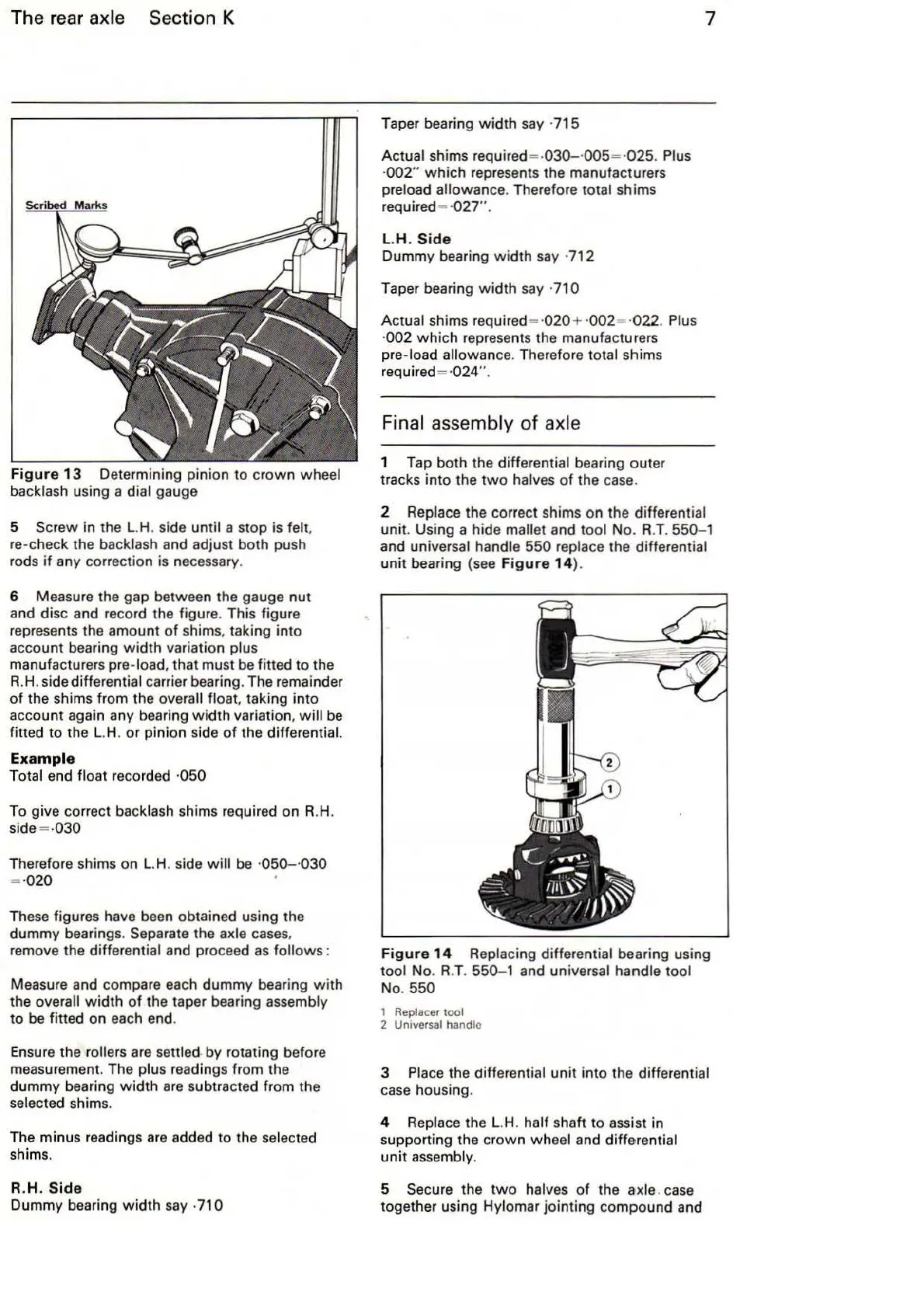
Fig
ur
e
13
Determining pinion to
crown
wheel
backlash using a dial gauge
5 Screw in the L.H. side until a stop is felt.
re-check the
ba
cklash and adjust both push
rods
if
any correction is
ne
cessary.
6 Measure the gap between the gauge nut
and disc and record the figure. This figure
represents the amount
of
shims, taking into
account bearing
width
variation plus
manufacturers pre-load. that must be fitted to the
R.H. side differential carrier bearing. The remainder
of
the shims from the overall float. taking into
account again any bearing
width
variation.
will
be
fitted to the
L.
H. or pinion side
of
the differential.
Exa
mple
Total end float recorded ·050
To give correct backlash shims required on R.H.
side= -030
Therefore shims on
L.H
. side
will
be
·
050-
·030
= ·020
These figures have been obtained using the
dummy bearings.
Separate the axle
cases
.
remove the differential and proceed
as
follows :
Measure and compare each dummy bearing
with
the overall
width
of
the taper bearing assembly
to be fitted on each end.
Ensure the
rollers are settled by rotating before
measurement. The plus readings from the
dummy bearing
width
are
subtracted from the
selected shi
ms.
The minus readings are added to the
se
lected
sh
ims.
R.H.
Sid
e
Dummy bearing
wi
dth say ·
71
0
Taper bearing
width
say ·715
Actual shims required= ·
030-
·005= ·
025
. Plus
·002"
which
represents the manufacturers
preload allowance. Therefore
total shims
required=
·
027"
.
l.H
. S
id
e
Dummy bearing
width
say · 712
Taper bearing
width
say ·710
Actual shims required = ·
020
+ ·002= ·
022
. Plus
·002
which
represents the manufacturers
pre-load allowance. Therefore total shims
required=
·024"
.
Fi
nal assembly of axle
1 Tap both the differential bearing outer
tracks into the
two
halves
of
the
case
.
7
2 Replace the correct shims on the differential
unit. Using a hide
mallet and tool No. R.T. 550-1
and universal handle 550 replace the differential
unit
bearing (see F
igu
re
14
).
Figu
re
14
Replacing differential bearing using
tool No. R.T.
550- 1 and universal handle tool
No. 550
1 Replacer tool
2
Un1versal handle
3 Place the differential
unit
into
the differential
case housing.
4 Replace the L.H. half shaft to assist in
supporting the crown wheel and
dif
ferential
un
it
assembly.
5 Secure the
two
ha
lves
of
the axle.
case
together using Hylomar jointing compound and