The brakes Section L
Figure
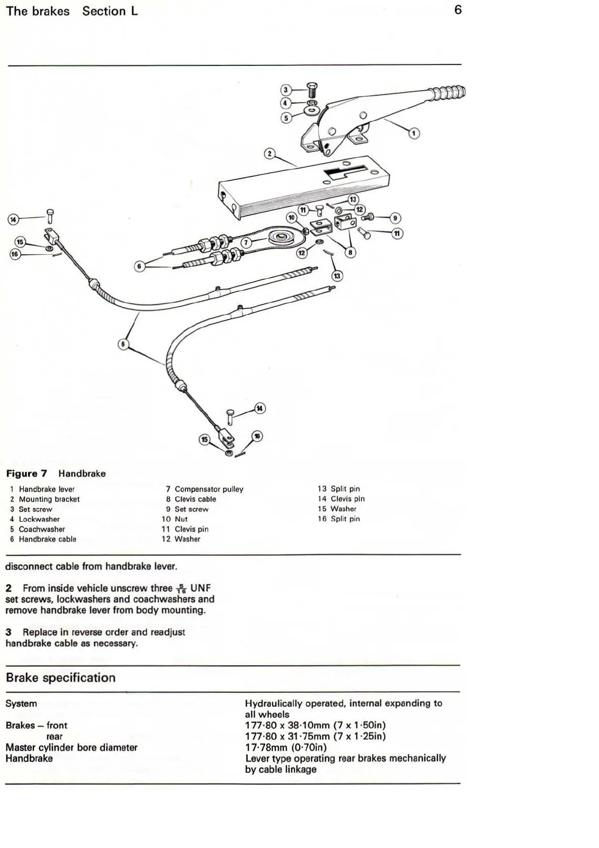
7 Handbrake
1 Handbrake l
eve
r
2 Mounting bracket
3 Set scr
ew
4 Lockwasher
5
Coa
chwasher
6 Handbrake
cable
7 Compensator pulley
8 Clevis
ca
bl
e
9 Set screw
10 Nut
1 1
Clevis pin
12
Washer
disconnect cable from handbrake lever.
2
Fr
om inside
ve
hicle unscrew three
-h
UNF
set screws, lockwashers and coachwashers and
remo
ve
handbrake lever from body mounting.
3 Replace in reverse order and readjust
handbrake cable
as
necessary.
Brake specification
System
Brakes - front
rear
Master cylinder bore diameter
Hand brake
13
Split pin
1 4 Clevis pin
15
W
asher
16 Split pin
Hydraulically operated, internal expanding
to
all wheels
177·80 x 38·10mm (7 x 1·50in)
177·
80
x 31·75mm (7 x 1·25in)
17·78mm
(0
·70in)
Lever type operating
rear
brakes mechanically
by
cable linkage
6