4
Figure
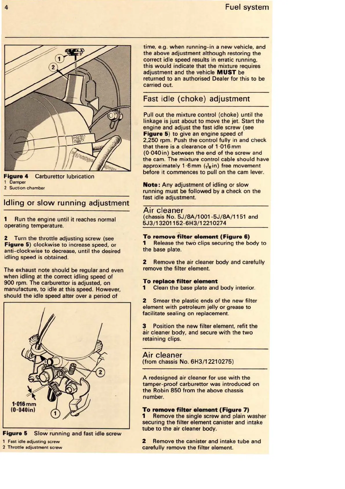
4 Carburettor lubrication
1 Damper
2 Suction chamber
Idling
or
slow
running adjustment
1 Run the engine until it reaches normal
operating temperature.
2 Turn the throttle adjusting sc
rew
{see
Figure
5) clockwise to increase speed, or
anti-clockwise to decrease, until the desired
idling speed is obtained.
The exhaust note should
be
regular and even
when idling
at
the correct idling speed
of
900
rpm. The carburettor
is
adjusted, on
manufacture,
to
idle at this speed. However,
should
the
idle speed alter over a period
of
Figure
& Slow running and fast idle screw
1
Fast
idle adjusting screw
2
Throttle adjustment screw
Fuel system
time, e.g. when running-in a
new
vehicle, and
the above adjustment although restoring the
correct idle speed
re
sults in erratic running,
this
would
indicate that the mixture requires
adjustment and the vehicle
MUST
be
returned
to
an
authorised Dealer for this
to
be
carried
out
.
Fast idle
(choke)
adjustment
Pull
out
the mixture control {choke) until the
linkage is just about to move the jet.
Start the
engine and adjust the fast idle screw {see
Figure
&)
to
give an engine speed
of
2.
250
rpm. Push the
cont
rol fully in and check
that there is a clearance
of
1 ·016 mm
{0·
040
in) between the end
of
the screw and
the cam. The
mi
xture control cable should have
appro
xi
mately 1 ·6 mm
{nin)
free movement
before
it
commences
to
pull on the cam lever.
Note
:
Any
adjustment
of
idling
or
slow
running must be followed by a check on the
fast idle adjustment.
Air
cleaner
{chassis
No
.
5J/8A/1
001
-5J/
8A
/ 1151 and
5J3
/132
01152-
6H3
/ 1221 0274
To
remove
filter
element
(Figure
6)
1 Release
the
two
clips securing the body to
the base plate.
2 Remove the air cleaner body and carefully
remove the filter element.
To
replace
filter
element
1 Clean
the
base plate and body interior.
2 Smear the plastic ends
of
the new filter
element
with
petroleum jelly or grease
to
facilitate
se
aling on replacement.
3 Position the
new
filter element, refit the
air cleaner bod
y,
and secure
with
the
two
retaining clips.
Air
cleaner
{from chassis
No
. 6H3/1221 0275)
A redesigned air cleaner for use
with
the
tamper-proof carburettor was
intr
oduced on
the Robin
8
50
from the above chassis
number.
To
remove
filter
element
(Figure
7)
1 Remove
the
single screw and plain washer
securing the filter element canister and intake
tube
to
the air cleaner body. ·
2 Remove the canister and intake tube and
ca
refully remove the filter element.