Steering Section D
1
Description
The steering mechanism compris
es
of
a single
stage
worm
on the end
of
the
lower
column
supported by
two
ball races located in the
steering box housing. Engaging the
worm
is a
spherical ended peg mounted in a ball
ra
ce
housed in the rocker shaft
which
in turn supports
a
dr
op arm linked
to
a track rod. The track rod
is connected to a steering arm bolted to the
stub axle
of
the front suspension assembly.
The upper
column, supported by a short outer
column secured
to
the engine bulkhead, is
clamped to a spline on the
low
er column.
Worm and peg wear can be taken
up
by the
rotation
of
the adjuster screw. End play in the
column can be eliminated by removing one
or
more shims located behind the steering
box
end plate.
Routine
ma
intenance
The steering box o
il
level should be checked
at regular intervals (see
Service Schedul
e)
and
topped
up
,
if
necessary,
at
the filler plug (see
F
igure
1 ).
Steering box
asse
mbly and steering
co
lumn
To
remove
(see
Figure
2)
1 Prise
off
steering wheel c
ra
sh
pad and
rem
ove~
UNF nut and plain washer securing
wheel to the steering column.
2
Rem
ove steering wheel from the splined
shaft
of
the steering column.
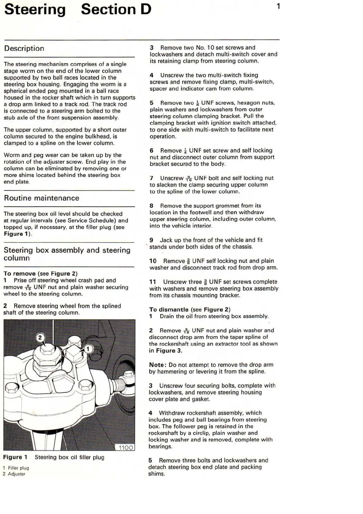
F
igu
re 1 Steering box oil filler plug
1
Fi
ller plug
2 Adjuster
3 Remove
two
No. 1 0 set screws and
lockwashers and detach multi-switch cover and
its retaining clamp from steering column.
4 Unscrew the
two
multi-switch fixing
screws and remove fixing
clamp,
multi-switch
,
spacer a
nd
indicator cam from column.
5 Remove t
wo
i UN F screws, hexagon nuts,
plain washers and lockwashers from outer
steering column clamping bracket. Pull the
clamping bracket
with
ignition
switch
attached,
to one side
with
multi-sw
it
ch to facilitate next
operation.
6 Remove
i UNF set screw and self locking
nut and disconnect outer column from support
bracket secured to the body.
7 Unscrew
-h
UNF bolt and
se
lf
locking nut
to
slacken the clamp securing upper column
to the spline
of
the l
owe
r column.
8 Remove the support grommet from its
location in the footwall and then
withd
r
aw
upper steering column, including outer column,
i
nto
the vehicle interior.
9 Jack
up
the front
of
the vehicle a
nd
fit
stands under both sides
of
the chassis.
10
Remove i UNF self locking nut and plain
washer and disconnect t
ra
ck rod from drop arm.
11 Unscrew thr
ee
i UNF set screws complete
with
washers and remove steering box assembly
from
it
s chassis mounting bracket.
To
dismant
le (see
Figu
re 2)
1 Drain the oil from steering box assembly.
2
Remove
~
UNF nut and plain washer and
disconnect drop arm from the taper spline
of
the rockershaft using an extractor tool
as
shown
in F
igure
3.
Not
e:
Do n
ot
attempt to remove the dr
op
arm
by hammering
or
levering
it
from the spline.
3 Unscrew four securing
bolts, complete
with
lockwashers, and remove steering housing
cover plate and gasket.
4
Withd
ra
w rockershaft assembly,
which
includes peg and ball bearings from steering
box. The follower peg is retained in the
rockershaft by a
circlip, plain washer and
locking washer and is
removed, complete
with
bearin
gs
.
5
Rem
ove three bolts and lockwashers and
detach steering box end plate a
nd
packing
shims.