Cooling system Section E
Figur
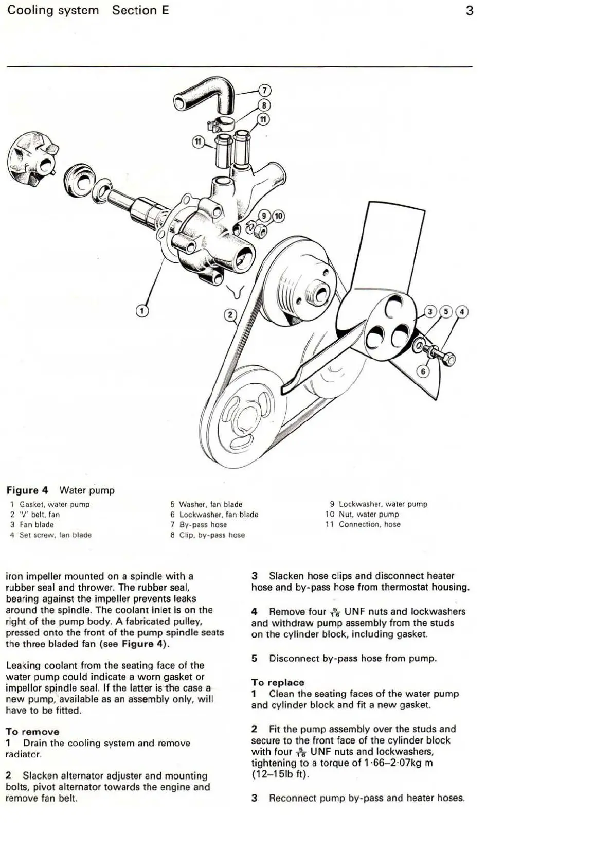
e 4 Water pump
1
Gas
kel.
wa
ler pump
3
5 W
as
h
er.
fan blade
2
·v·
be
ll
. f
an
3
Fan
bl
ade
6 Lockwasher. f
an
bl
ad
e
7
By·
pass
hose
9 Lockwasher.
wa
ler pump
10
Nul.
waler
pump
11
Conneclion. hose
4
Se
l screw. fan blade 8 Chp, by-pass hose
iron impeller mounted on a spindle
with
a
rubber seal and thr
owe
r. The rubber seal,
bearing against the impeller prevents leaks
around the spindle. The coolant inlet is on the
right
of
the pump
body
. A fabricated pulley,
pressed onto the front
of
the pump spindle seats
the three bladed fan (see
Figure
4}.
Leaking coolant from the seating face
of
the
water pump could indicate a worn gasket or
impellor spindle
sea
l.
If the latter is
the
case
a
new pump, available
as
an assembly only,
wi
ll
have to be fitted.
To
remove
1 Dr
ai
n the cooling system and remove
radiator.
2 Slacken alternator adjuster and mounting
bolts, pivot alternator towards the engine and
remove fan belt.
3 Slacken hose clips and disconnect heater
hose
an
d by-pass ho
se
from thermostat housing.
4
Rem
ove four
-h
UNF nuts and Jockwashers
and
withdraw
pump assembly from the studs
on the cy
li
nder block, including gasket.
5 Disconnect by-pass hose from pump.
To
replace
1 Clean the seating faces of the water pump
and cylinder block and
fit
a
new
gasket.
2 Fit the pump assembly over the studs and
secure to the front face
of
the cylinder block
with
four
-h
UN F nuts and lockwashe
rs
,
tightening to a torque
of
1·66- 2·07kg m
(12
-
15
lb
ft}
.
3 Reconnect pump by-pass and heater hoses.