Robin
850
Workshop
Manual
Supplement
The engine
23
Remove the four nuts securing the rocker
shaft. Remove the rocker shaft
assembly.
24
Remove the eight push rods. carefully
noting their correct order for subsequent
replacement.
2&
Disconnect the downpipe from the
exhaust
manifold. secured by
two
nuts.
28
Remove the three nuts and lockwashers
securing the cylinder head
to
the cylinder
block
on the spark plug side.
27
Remove the three bolts
sec
uring the
thermostat housing to the
cylinder head.
28
Remove the
nut
securing the dipstick
support bracket and earth
lead to the cylinder
head.
29
Remove the
12
nuts and washers
securing the
cylinder head
to
the cylinder
block
studs.
30
Remove by-pass hose from thermostat
housing. fitted on
ea
rly vehicles only.
3~
~arefully
lift
the cylinder head complete
w1th
mlet and exhaust manifolds from the
cylinder block. Replace in reverse order. after
cleaning the cylinder head and block faces
and fitting a new gasket.
To ensure a good
seal
when replacing the
cylinder head. smear gr
ease
around the metal
edges
of
the gasket bore eyelets.
Tighten the cylinder head nuts to a torque
of
3·_46kgm (25·01bft) in the sequence shown in
F1gure
13
. The three
nut
s fitted
to
the spark
plug side
of
the cylinder head should be
tightened
to
a torque of 2·
07kgm
(151
bft)
.
Figure
13
Cylinder head
nut
tightening sequence
11
Operation 1 0 - Cylind
er
head
decarbonise (
with
cylinder h
ea
d
removed)
1 Remove the spark plugs.
2
~amove
the nuts and lockwashers securing
the
mlet and exhaust manifolds
to
the cylind
er
head. Remove the manifolds and carefully
remove the manifold gasket.
3 U
si
ng a suitable valve spring compression
tool. remove the valves from the cylinder head.
keeping in correct order. Retain the
valve
springs. cups and cotters f
or
inspection.
4 Check the inlet and exhaust valve guides
fo
r wear and renew if
ne
cessary.
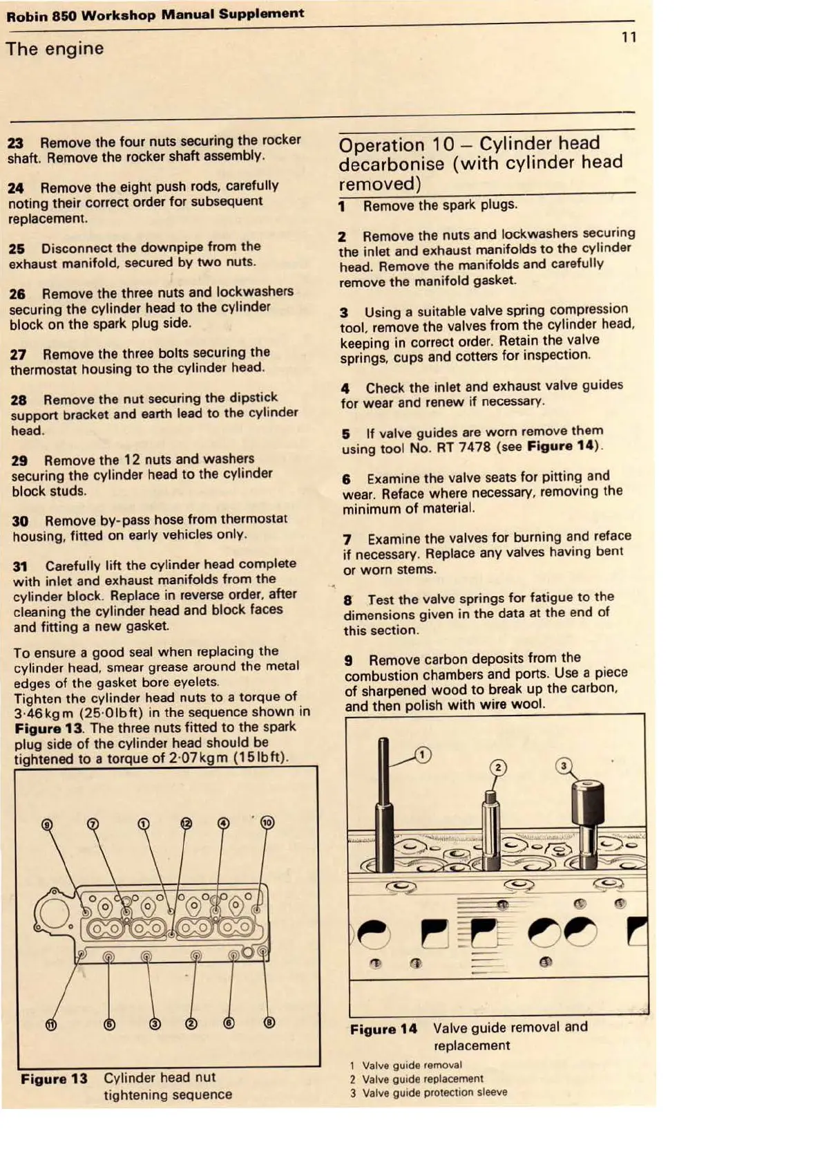
&
If
valve guides are worn remove them
using
tool No.
RT
7478 (s
ee
Figure
14
).
8 Examine the valve
sea
ts for pitting and
wear. Reface where necessary. removing the
minimum
of
material.
7 Examine the valves f
or
burning and reface
if
necessary. Replace any valves having bent
or
worn
st
ems.
8 Test the valve springs for fatigue to
th
e
dimensio
ns
given in the data at the end
of
this section.
9 Remove carbon deposits from the
combustion chambers and ports. Use a piece
of
sha
rpened
wood
to
break up the carbon.
and then
polish
wi
th
wire
woo
l.
Figure
14
Valve guide removal and
replacement
1 Valve guide removal
2 Valve
guide
replacement
3 Valve
gu1de
protection sleeve