The driveshaft
Section
J
1
Description
The drive shaft comprises
two
sections,
incorporating a
sliding spline and universal
joints
to
allow
fore and aft movement
of
the
rear
axle.
Each
universal
joint
consists
of
a centre
spider, four
needle bearings and
two
yokes.
Routine maintenance
Three lubrication points are provided, one each
on
the universal joints, and one on the gearbox
end
of
the shaft
to
enable greasing
of
the sliding
spline.
Grease should be applied to these points
every
3,000 miles (5,000km).
To remove drive shaft
1
If
a ramp is
not
available jack
up
the vehicle
and
fit
stands under the chassis.
2 Unscrew four
bolts and nuts, complete
with
lockwashers from the coupling flanges at
gearbox and
axle ends
of
the drive shaft and
li
ft
drive shaft cl
ear.
Checking drive shaft for wear
The degree
of
wear
on
the driveshaft thrust faces
can be determined by the amount
of
lift
in
the
joints. This can be measured by hand using a
piece
of
wood
suitably pivotted. Any
circumferential movement
of
the shaft relative
to
the coupling flange yokes indicates wear
in
the needle roller bearings, or drive shaft spline,
or ovality in the yokes. A Un
it
Package (Journal
Kit) is available for replacing worn needle
bearings and journals
but
if
excessive wear is
apparent on the yoke bearing seatings or drive
shaft
splines a
new
complete unit
will
have to
be fitted.
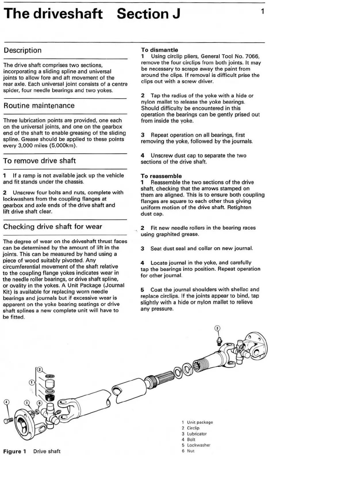
Figur
e 1 Drive shaft
To
dismantle
1 Using circlip plier
s,
General Tool No. 7066,
remove the four circlips from both joints.
It
may
be necessary to scrape away the paint from
around the
clips. If removal is difficult prise the
clips out
with
a screw driver.
2 Tap the radius
of
the yoke
with
a hide or
nylon mallet
to
release the yoke bearings.
Should difficulty be encountered in this
operation the bearings can be
gently prised out
from inside the yoke.
3 Repeat operation on all bearings, first
removing the yoke,
followed
by
the journals.
4 Unscrew dust cap to separate the
two
sections
of
the drive shaft.
To
re
assemb
le
1 Reassemble the
two
sections
of
the drive
shaft, checking that the arrows stamped
on
them are aligned. This is to ensure both coupling
flanges are square
to
each other thus giving
uniform motion
of
the drive shaft. Retighten
dust cap.
2 Fit
new
needle rollers in the bearing races
using graphited grease.
3 Seat dust seal and collar on
new
journal.
4 Locate journal in the yoke, and carefully
tap the bearings into position. Repeat operation
for other
journal.
5 Coat the journal shoulders
with
shellac and
replace circlips.
If
the joints appear to bind, tap
slightly
with
a hide or nylon mallet to relieve
any pressure.
1 Unit package
2 Circlip
3 Lubricator
4 Bolt
5 Lockwasher
6 Nut