RL78/G13 CHAPTER 3 CPU ARCHITECTURE
R01UH0146EJ0100 Rev.1.00 116
Sep 22, 2011
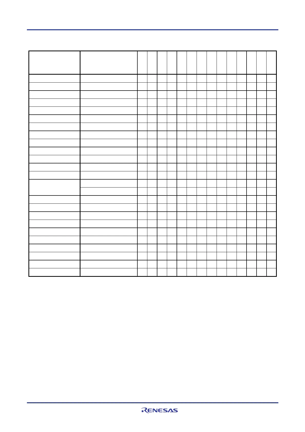
Table 3-3. Vector Table (2/2)
Vector Table Address Interrupt Source
128-pin
100-pin
80-pin
64-pin
52-pin
48-pin
44-pin
40-pin
36-pin
32-pin
30-pin
25-pin
24-pin
20-pin
0042H INTTM04
√ √ √ √ √ √ √ √ √ √ √ √ √ √
0044H INTTM05
√ √ √ √ √ √ √ √ √ √ √ √ √ √
0046H INTTM06
√ √ √ √ √ √ √ √ √ √ √ √ √ √
0048H INTTM07
√ √ √ √ √ √ √ √ √ √ √ √ √ √
004AH INTP6
√ √ √ √ √ √ − − − − − − − −
004CH INTP7
√ √ √ √ − − − − − − − − − −
004EH INTP8
√ √ √ √ √ √ − − − − − − − −
0050H INTP9
√ √ √ √ √ √ − − − − − − − −
0052H INTP10
√ √ √ √ √ − − − − − − − − −
0054H INTP11
√ √ √ √ √ − − − − − − − − −
0056H INTTM10
√ √ √ − − − − − − − − − − −
0058H INTTM11
√ √ √ − − − − − − − − − − −
005AH INTTM12
√ √ √ − − − − − − − − − − −
005CH INTSRE3
√ √ √ − − − − − − − − − − −
INTTM13H
√ √ √ − − − − − − − − − − −
005EH INTMD
√ √ √ √ √ √ √ √ √ √ √ √ √ √
0060H INTIICA1
√ √ √ − − − − − − − − − − −
0062H INTFL
√ √ √ √ √ √ √ √ √ √ √ √ √ √
0064H INTDMA2
√ √ √ − − − − − − − − − − −
0066H INTDMA3
√ √ √ − − − − − − − − − − −
0068H INTTM14
√ − − − − − − − − − − − − −
006AH INTTM15
√ − − − − − − − − − − − − −
006CH INTTM16
√ − − − − − − − − − − − − −
006EH INTTM17
√ − − − − − − − − − − − − −
007EH BRK
√ √ √ √ √ √ √ √ √ √ √ √ √ √
(2) CALLT instruction table area
The 64-byte area 00080H to 000BFH can store the subroutine entry address of a 2-byte call instruction (CALLT). Set
the subroutine entry address to a value in a range of 00000H to 0FFFFH (because an address code is of 2 bytes).
To use the boot swap function, set a CALLT instruction table also at 01080H to 010BFH.
(3) Option byte area
A 4-byte area of 000C0H to 000C3H can be used as an option byte area. Set the option byte at 010C0H to 010C3H
when the boot swap is used. For details, see CHAPTER 24 OPTION BYTE.
(4) On-chip debug security ID setting area
A 10-byte area of 000C4H to 000CDH and 010C4H to 010CDH can be used as an on-chip debug security ID setting
area. Set the on-chip debug security ID of 10 bytes at 000C4H to 000CDH when the boot swap is not used and at
000C4H to 000CDH and 010C4H to 010CDH when the boot swap is used. For details, see CHAPTER 26 ON-CHIP
DEBUG FUNCTION.

 Loading...


