RL78/G13 CHAPTER 4 PORT FUNCTIONS
R01UH0146EJ0100 Rev.1.00 177
Sep 22, 2011
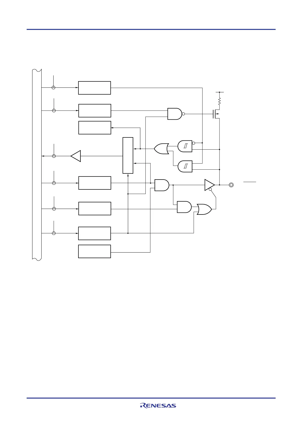
For example, figures 4-7 to 4-14 show block diagrams of port 1 for 128-pin products when PIOR = 00H.
Figure 4-7. Block Diagram of P10
P10/SCK00/SCL00
WR
PU
RD
WR
PORT
PU10
EVDD
P-ch
PU1
P1
WRPM
PM1
POM10
POM1
WRPOM
PM10
CMOS
TTL
PIM1
PIM10
WRPIM
Output latch
(P10)
Selector
Alternate
function
Alternate
function
Internal bus
P1: Port register 1
PU1: Pull-up resistor option register 1
PM1: Port mode register 1
PIM1: Port input mode register 1
POM1: Port output mode register 1
RD: Read signal
WR××: Write signal
<R>

 Loading...


