RL78/G13 CHAPTER 4 PORT FUNCTIONS
R01UH0146EJ0100 Rev.1.00 186
Sep 22, 2011
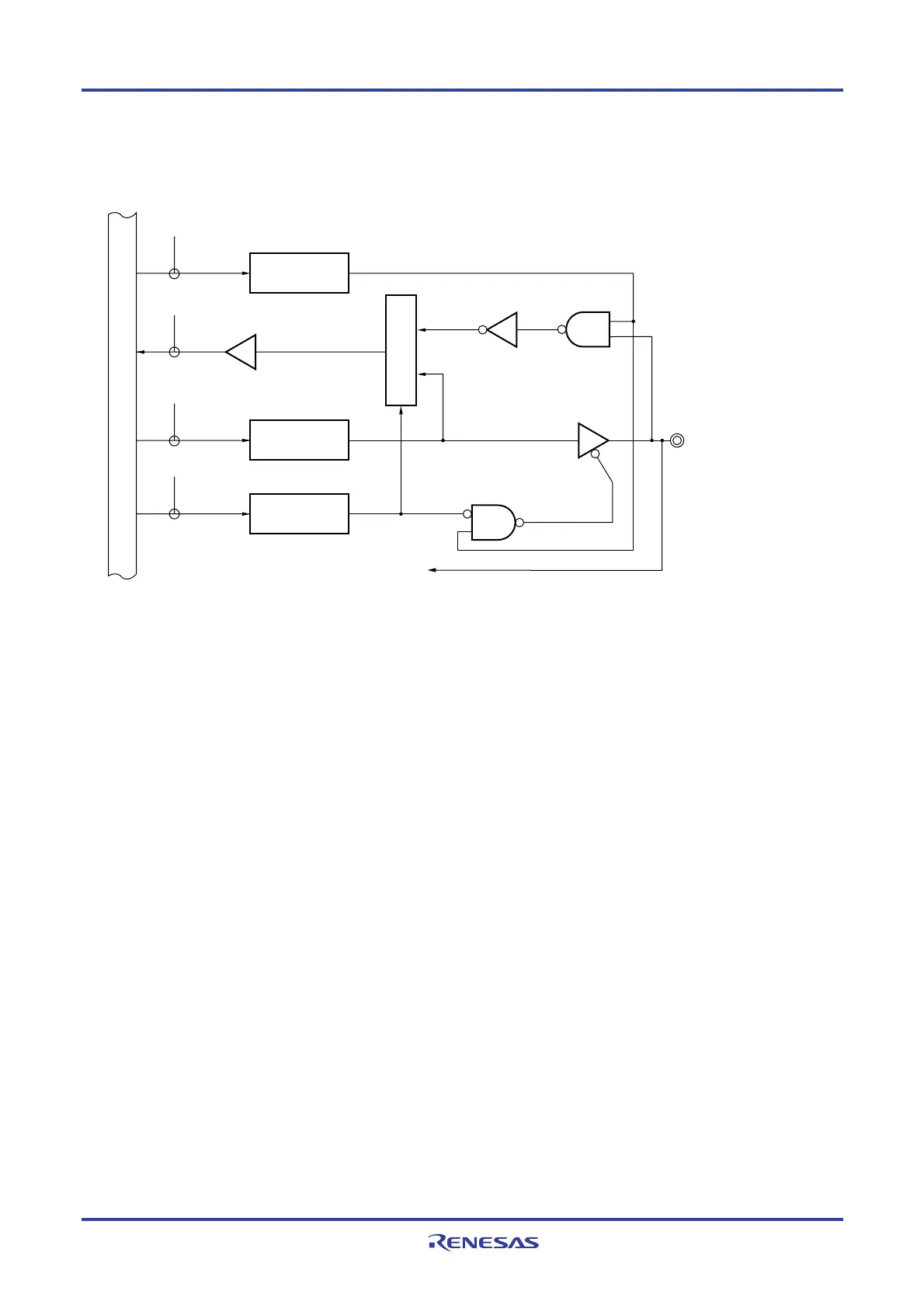
For example, figure 4-15 shows a block diagram of port 2 for 128-pin products when PIOR = 00H.
Figure 4-15. Block Diagram of P20 to P27
P20/ANI0/AVREFP,
P21/ANI1/AV
REFM,
P22/ANI2 to P27/ANI7
RD
WR
PORT
WRPM
PM20 to PM27
PM2
A/D converter
P2
Output latch
(P20 to P27)
Selector
Internal bus
WRADPC
ADPC3 to ADPC0
ADPC
0:Analog input
1:Digital I/O
ADPC: A/D port configuration register
P2: Port register 2
PM2: Port mode register 2
RD: Read signal
WR××: Write signal
<R>
<R>

 Loading...


