RL78/G13 CHAPTER 5 CLOCK GENERATOR
R01UH0146EJ0100 Rev.1.00 313
Sep 22, 2011
Table 5-3 shows transition of the CPU clock and examples of setting the SFR registers.
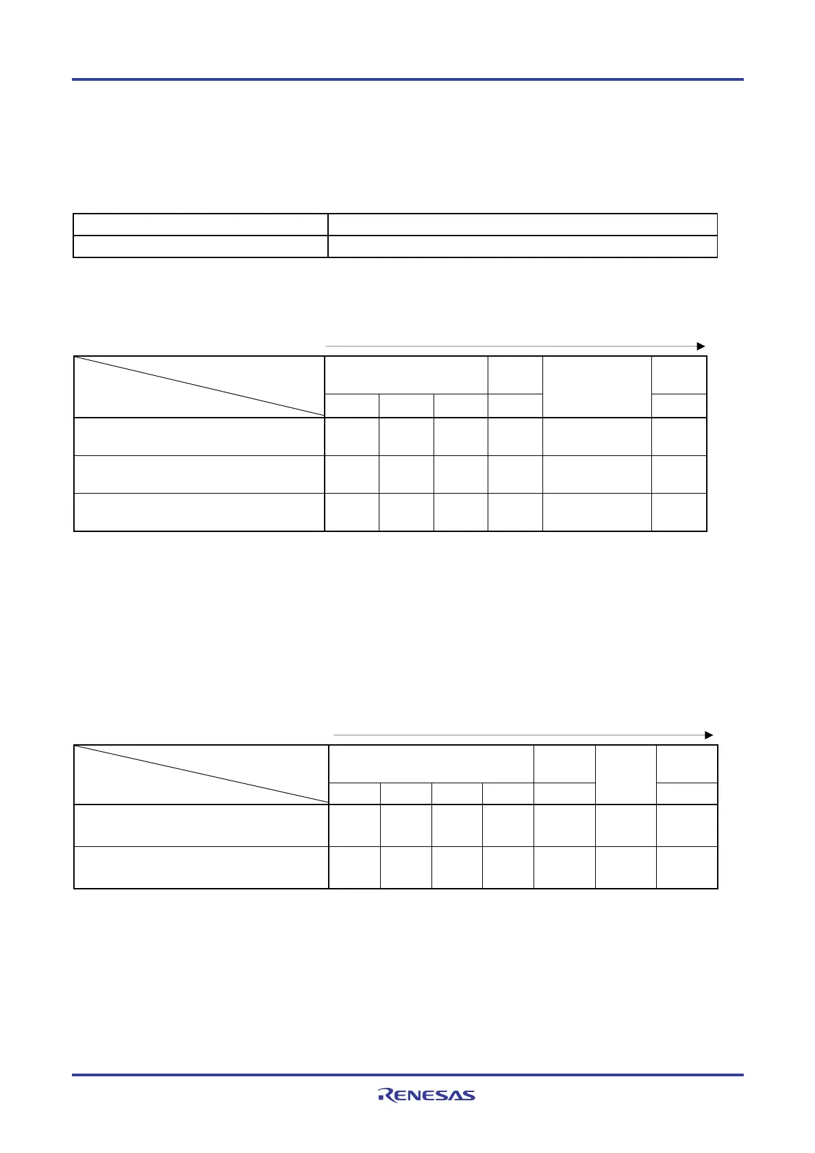
Table 5-3. CPU Clock Transition and SFR Register Setting Examples (1/5)
(1) CPU operating with high-speed on-chip oscillator clock (B) after reset release (A)
Status Transition SFR Register Setting
(A) → (B) SFR registers do not have to be set (default status after reset release).
(2) CPU operating with high-speed system clock (C) after reset release (A)
(The CPU operates with the high-speed on-chip oscillator clock immediately after a reset release (B).)
(Setting sequence of SFR registers)
CMC Register
Note
CSC
Register
CKC
Register
Setting Flag of SFR Register
Status Transition
EXCLK OSCSEL AMPH MSTOP
OSTC Register
MCM0
(A) → (B) → (C)
(X1 clock: 1 MHz ≤ f
X ≤ 10 MHz)
0 1 0 0 Must be checked 1
(A) → (B) → (C)
(X1 clock: 10 MHz < f
X ≤ 20 MHz)
0 1 1 0 Must be checked 1
(A) → (B) → (C)
(external main clock)
1 1
×
0 Must not be checked 1
Note The clock operation mode control register (CMC) can be written only once by an 8-bit memory manipulation
instruction after reset release.
Caution Set the clock after the supply voltage has reached the operable voltage of the clock to be set (see
CHAPTER 29 ELECTRICAL SPECIFICATIONS.
(3) CPU operating with subsystem clock (D) after reset release (A)
(The CPU operates with the high-speed on-chip oscillator clock immediately after a reset release (B).)
(Setting sequence of SFR registers)
CMC Register
Note
CSC
Register
CKC
Register
Setting Flag of SFR Register
Status Transition
EXCLKS OSCSELS
AMPHS1 AMPHS0 XTSTOP
Waiting for
Oscillation
Stabilization
CSS
(A) → (B) → (D)
(XT1 clock)
0 1 0/1 0/1 0 Necessary 1
(A) → (B) → (D)
(external sub clock)
1 1
× ×
0 Necessary 1
Note The clock operation mode control register (CMC) can be written only once by an 8-bit memory manipulation
instruction after reset release.
Remarks 1. ×: don’t care
2. (A) to (J) in Table 5-3 correspond to (A) to (J) in Figure 5-15.

 Loading...


