RL78/G13 CHAPTER 6 TIMER ARRAY UNIT
R01UH0146EJ0100 Rev.1.00 381
Sep 22, 2011
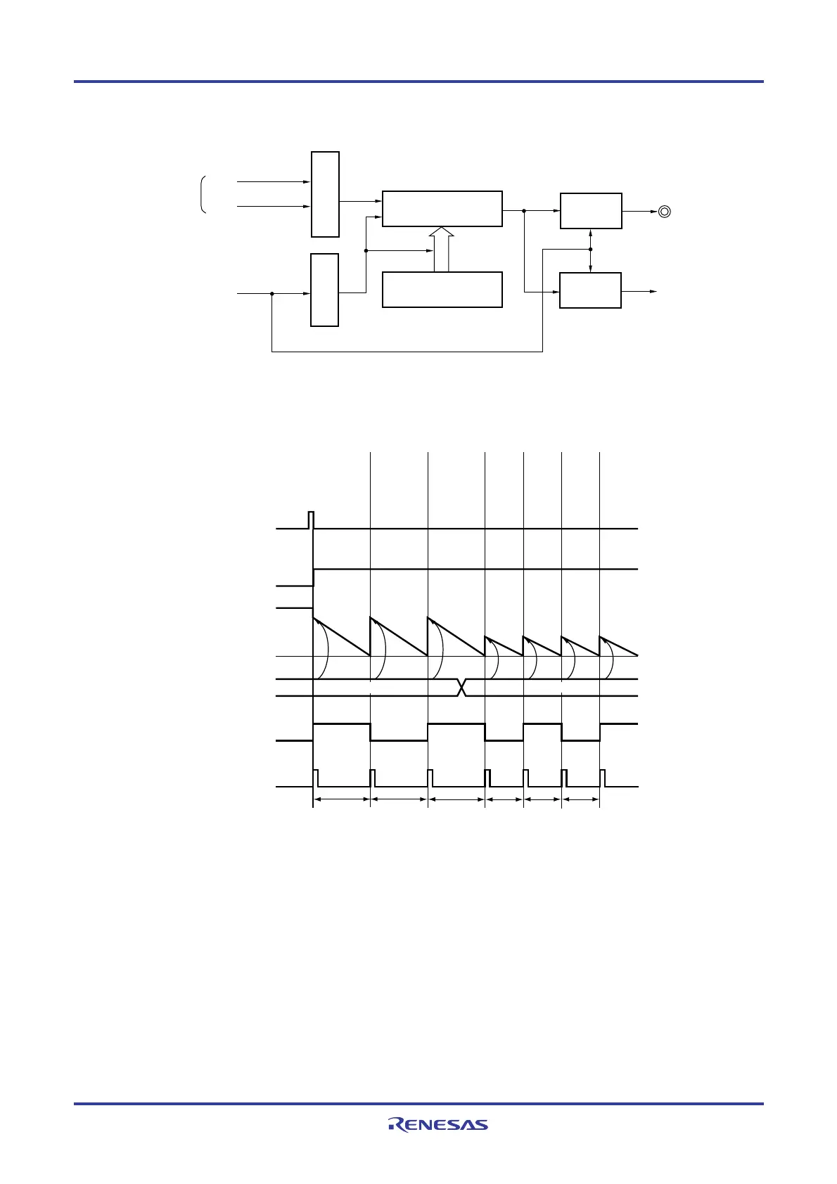
Figure 6-37. Block Diagram of Operation as Interval Timer/Square Wave Output
CKm0
CKm1
TSmn
Timer counter
register mn (TCRmn)
TOmn pin
Interrupt signal
(INTTMmn)
Timer data
register mn(TDRmn)
Interrupt
controller
Output
controller
Clock selection
Trigger selection
Operation clock
Note
Note When channels 1 and 3, the clock can be selected from CKm0, CKm1, CKm2 and CKm3.
Figure 6-38. Example of Basic Timing of Operation as Interval Timer/Square Wave Output (MDmn0 = 1)
TSmn
TEmn
TDRmn
TCRmn
TOmn
INTTMmn
a
a+1
b
0000H
a+1
a+1
b+1
b+1 b+1
Remarks 1. m: Unit number (m = 0, 1), n: Channel number (n = 0 to 7)
2. TSmn: Bit n of timer channel start register m (TSm)
TEmn: Bit n of timer channel enable status register m (TEm)
TCRmn: Timer count register mn (TCRmn)
TDRmn: Timer data register mn (TDRmn)
TOmn: TOmn pin output signal
<R>

 Loading...


