RL78/G13 CHAPTER 11 A/D CONVERTER
R01UH0146EJ0100 Rev.1.00 495
Sep 22, 2011
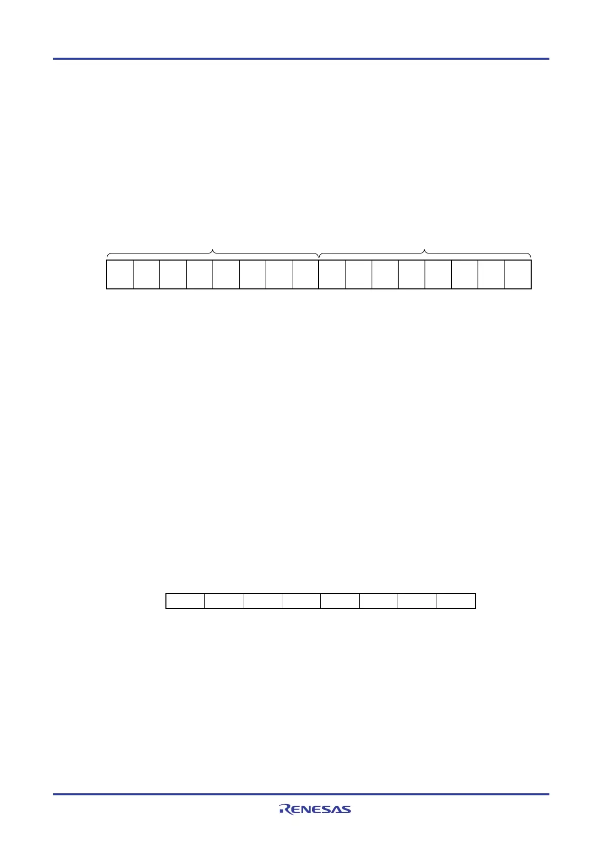
(5) 10-bit A/D conversion result register (ADCR)
This register is a 16-bit register that stores the A/D conversion result in the select mode. The lower 6 bits are fixed to
0. Each time A/D conversion ends, the conversion result is loaded from the successive approximation register (SAR).
The higher 8 bits of the conversion result are stored in FFF1FH and the lower 2 bits are stored in the higher 2 bits of
FFF1EH.
The ADCR register can be read by a 16-bit memory manipulation instruction.
Reset signal generation clears this register to 0000H.
Figure 11-9. Format of 10-bit A/D Conversion Result Register (ADCR)
Symbol
Address: FFF1FH, FFF1EH After reset: 0000H R
FFF1FH FFF1EH
000000
ADCR
Cautions 1. When writing to the A/D converter mode register 0 (ADM0), analog input channel specification
register (ADS), and A/D port configuration register (ADPC), the contents of the ADCR register
may become undefined. Read the conversion result following conversion completion before
writing to the ADM0, ADS, and ADPC registers. Using timing other than the above may cause an
incorrect conversion result to be read.
2. When 8-bit resolution A/D conversion is selected (when the ADTYP bit of A/D converter mode
register 2 (ADM2) is 1) and the ADCR register is read, 0 is read from the lower two bits (ADCR1
and ADCR0).
3. When the ADCR register is accessed in 16-bit units, the higher 10 bits of the conversion result
are read in order starting at bit 15.
(6) 8-bit A/D conversion result register (ADCRH)
This register is an 8-bit register that stores the A/D conversion result. The higher 8 bits of 10-bit resolution are stored.
The ADCRH register can be read by an 8-bit memory manipulation instruction.
Reset signal generation clears this register to 00H.
Figure 11-10. Format of 8-bit A/D Conversion Result Register (ADCRH)
Symbol
ADCRH
Address: FFF1FH After reset: 00H R
76543210
Caution When writing to the A/D converter mode register 0 (ADM0), analog input channel specification
register (ADS), and A/D port configuration register (ADPC), the contents of the ADCRH register may
become undefined. Read the conversion result following conversion completion before writing to
the ADM0, ADS, and ADPC registers. Using timing other than the above may cause an incorrect
conversion result to be read.

 Loading...


