RL78/G13 CHAPTER 11 A/D CONVERTER
R01UH0146EJ0100 Rev.1.00 526
Sep 22, 2011
(1) If an interrupt is generated after A/D conversion ends
If the A/D conversion result value is inside the range of values specified by the A/D conversion result comparison
function (which is set up by using the ADRCK bit and ADUL/ADLL register), the A/D conversion end interrupt request
signal (INTAD) is generated.
• While in the select mode
After A/D conversion ends and the A/D conversion end interrupt request signal (INTAD) is generated, the clock
request signal remains at the high level, and the A/D converter switches from the SNOOZE mode to the normal
operation mode. To stop the high-speed on-chip oscillator clock supplied while in the SNOOZE mode, clear bit 2
(AWC) of A/D converter mode register 2 (ADM2) to 0. Doing this sets the clock request signal (an internal signal) to
the low level and stops the supply of the high-speed on-chip oscillator clock.
• While in the scan mode
If even one A/D conversion end interrupt request signal (INTAD) is generated during A/D conversion of the four
channels, the clock request signal remains at the high level, and the A/D converter switches from the SNOOZE
mode to the normal operation mode. To stop the high-speed on-chip oscillator clock supplied while in the SNOOZE
mode, clear bit 2 (AWC) of A/D converter mode register 2 (ADM2) to 0. Doing this sets the clock request signal (an
internal signal) to the low level and stops the supply of the high-speed on-chip oscillator clock.
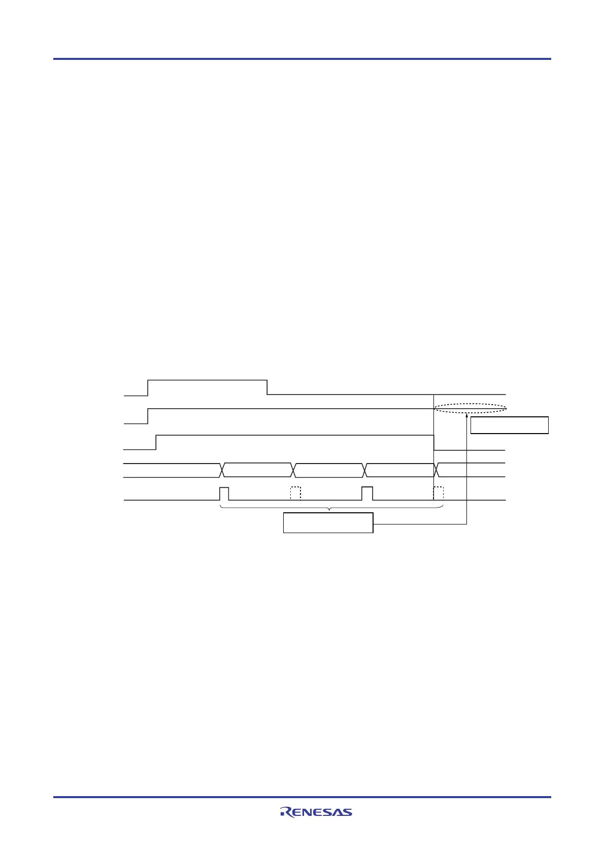
Figure 11-38. Operation Example When Interrupt Is Generated After A/D Conversion Ends (While in Scan Mode)
ADCS
Interrupt signal
(INTAD)
INTRTC
Clock request signal
(internal signal)
Conversion
channels
Channel 1 Channel 2 Channel 3 Channel 4
An interrupt is generated
when conversion on one
of the channels ends.
The clock request signal
remains at the high level.
<R>