RL78/G13 CHAPTER 12 SERIAL ARRAY UNIT
R01UH0146EJ0100 Rev.1.00 652
Sep 22, 2011
(1) Register setting
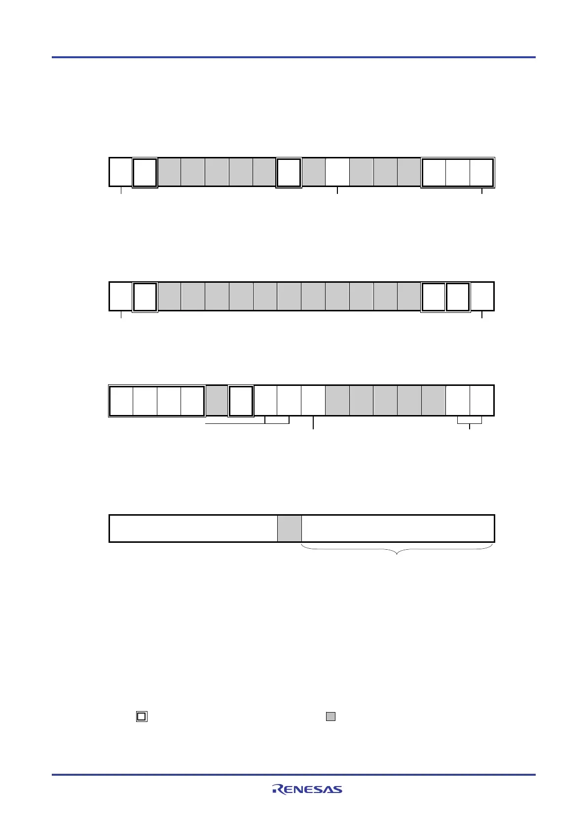
Figure 12-85. Example of Contents of Registers for UART Reception of UART
(UART0 to UART3) (1/2)
(a) Serial mode register mn (SMRmn)
15 14 13 12 11 10 9 8 7 6 5 4 3 2 1 0
SMRmn
CKSmn
0/1
CCSmn
0
0
0
0
0
0
STSmn
1
0
SISmn0
0/1
1
0
0
MDmn2
0
MDmn1
1
MDmn0
0
Operation clock (fMCK) of channel n
0: Prescaler output clock CKm0
set by the SPSm register
1: Prescaler output clock CKm1
set by the SPSm register
0: Forward (normal) reception
1: Reverse reception
Operation mode of channel n
0: Transfer end interrupt
(b) Serial mode register mr (SMRmr)
15 14 13 12 11 10 9 8 7 6 5 4 3 2 1 0
SMRmr
CKSmr
0/1
CCSmr
0
0
0
0
0
0
0
0
0
1
0
0
MDmr2
0
MDmr1
1
MDmr0
0/1
Same setting value as CKSmn
bit
Operation mode of channel r
0: Transfer end interrupt
1: Buffer empty interrupt
(c) Serial communication operation setting register mn (SCRmn)
15 14 13 12 11 10 9 8 7 6 5 4 3 2 1 0
SCRmn
TXEmn
0
RXEmn
1
DAPmn
0
CKPmn
0
0
EOCmn
1
PTCmn1
0/1
PTCmn0
0/1
DIRmn
0/1
0
0
0
0
1
DLSmn1
0/1
DLSmn0
0/1
Setting of parity bit
00B: No parity
01B: No parity judgment
10B: Appending Even parity
11B: Appending Odd parity
Selection of data transfer sequence
0: Inputs/outputs data with MSB first
1: Inputs/outputs data with LSB first.
Setting of data length
(d) Serial data register mn (SDRmn) (lower 8 bits: RXDq)
15 14 13 12 11 10 9 8 7 6 5 4 3 2 1 0
SDRmn
Baud rate setting
0
Note
Receive data register
Note When UART performs 9-bit communication, bits 0 to 8 of the SDRm1 register are used as the transmission
data specification area. Only following UARTs can be specified for the 8-bit data length.
• 24 to 64-pin products: UART0
• 80, 100, 128-pin products: UART0 and UART2
Caution For the UART reception, be sure to set the SMRmr register of channel r to UART transmission mode
that is to be paired with channel n.
Remarks 1. m: Unit number (m = 0, 1), n: Channel number (n = 1, 3), mn = 01, 03, 11, 13
r: Channel number (r = n − 1), q: UART number (q = 0 to 3)
2. : Setting is fixed in the UART reception mode, : Setting disabled (set to the initial value)
×: Bit that cannot be used in this mode (set to the initial value when not used in any mode)
0/1: Set to 0 or 1 depending on the usage of the user
RXDq
<R>

 Loading...


