RL78/G13 CHAPTER 16 INTERRUPT FUNCTIONS
R01UH0146EJ0100 Rev.1.00 830
Sep 22, 2011
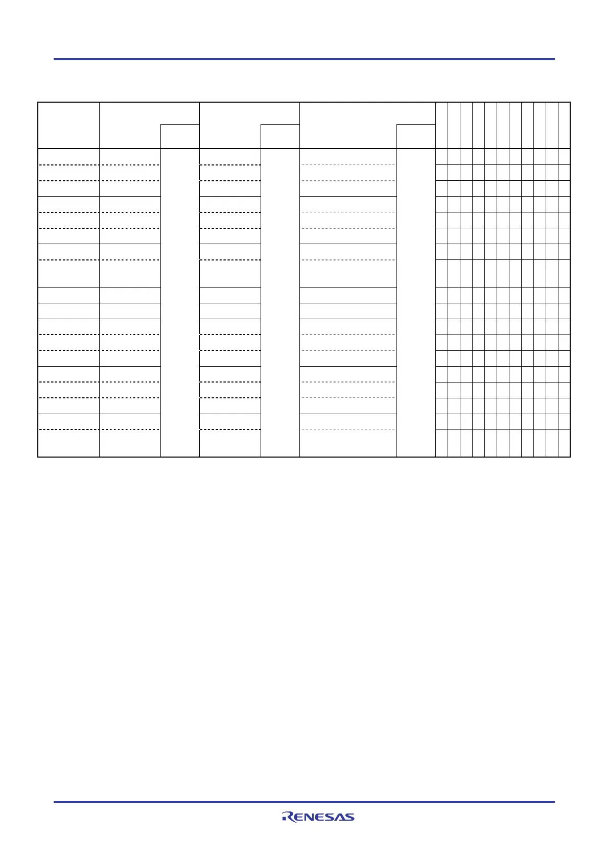
Table 16-2. Flags Corresponding to Interrupt Request Sources (2/4)
Interrupt Request Flag Interrupt Mask Flag Priority Specification Flag Interrupt
Source
Register Register Register
128-pin
100-pin
80-pin
64-pin
52-pin
48-pin
40, 44-pin
36-pin
30, 32-pin
24, 25-pin
20-pin
INTST2
Note 1
STIF2
Note 1
STMK2
Note 1
STPR02, STPR12
Note 1
√ √ √ √ √ √ √ √ √ − −
INTCSI20
Note 1
CSIIF20
Note 1
CSIMK20
Note 1
CSIPR020, CSIPR120
Note 1
√ √ √ √ √ √ √ √ √ − −
INTIIC20
Note 1
IICIF20
Note 1
IICMK20
Note 1
IICPR020, IICPR120
Note 1
√ √ √ √ √ √ √ √ √ − −
INTSR2
Note 2
SRIF2
Note 2
SRMK2
Note 2
SRPR02, SRPR12
Note 2
√ √ √ √ √ √ √ √ √ − −
INTCSI21
Note 2
CSIIF21
Note 2
CSIMK21
Note 2
CSIPR021, CSIPR121
Note 2
√ √ √ √ √ √ √ √ − − −
INTIIC21
Note 2
IICIF21
Note 2
IICMK21
Note 2
IICPR021, IICPR121
Note 2
√ √ √ √ √ √ √ √ − − −
INTSRE2
Note 3
SREIF2
Note 3
SREMK2
Note 3
SREPR02, SREPR12
Note 3
√ √ √ √ √ √ √ √ √ − −
INTTM11H
Note 3
TMIF11H
Note 3
TMMK11H
Note 3
TMPR011H, TMPR111H
Note 3
√ √ √ − − − − − − − −
INTDMA0 DMAIF0 DMAMK0 DMAPR00, DMAPR10
√ √ √ √ √ √ √ √ √ √ √
INTDMA1 DMAIF1 DMAMK1 DMAPR01, DMAPR11
√ √ √ √ √ √ √ √ √ √ √
INTST0
Note 4
STIF0
Note 4
STMK0
Note 4
STPR00, STPR10
Note 4
√ √ √ √ √ √ √ √ √ √ √
INTCSI00
Note 4
CSIIF00
Note 4
CSIMK00
Note 4
CSIPR000, CSIPR100
Note 4
√ √ √ √ √ √ √ √ √ √ √
INTIIC00
Note 4
IICIF00
Note 4
IICMK00
Note 4
IICPR000, IICPR100
Note 4
√ √ √ √ √ √ √ √ √ √ √
INTSR0
Note 5
SRIF0
Note 5
SRMK0
Note 5
SRPR00, SRPR10
Note 5
√ √ √ √ √ √ √ √ √ √ √
INTCSI01
Note 5
CSIIF01
Note 5
CSIMK01
Note 5
CSIPR001, CSIPR101
Note 5
√ √ √ √ √ √ − − − − −
INTIIC01
Note 5
IICIF01
Note 5
IICMK01
Note 5
IICPR001, IICPR101
Note 5
√ √ √ √ √ √ − − − − −
INTSRE0
Note 6
SREIF0
Note 6
SREMK0
Note 6
SREPR00, SREPR10
Note 6
√ √ √ √ √ √ √ √ √ √ √
INTTM01H
Note 6
TMIF01H
Note 6
IF0H
TMMK01H
Note 6
MK0H
TMPR001H, TMPR101H
Note 6
PR00H,
PR10H
√ √ √ √ √ √ √ √ √ √ √
Notes 1. Do not use UART2, CSI20, and IIC20 at the same time because they share flags for the interrupt request
sources. If one of the interrupt sources INTST2, INTCSI20, and INTIIC20 is generated, bit 0 of the IF0H
register is set to 1. Bit 0 of the MK0H, PR00H, and PR10H registers supports these three interrupt sources.
2. Do not use UART2, CSI21, and IIC21 at the same time because they share flags for the interrupt request
sources. If one of the interrupt sources INTSR2, INTCSI21, and INTIIC21 is generated, bit 1 of the IF0H
register is set to 1. Bit 1 of the MK0H, PR00H, and PR10H registers supports these three interrupt sources.
3. Do not use UART2 and channel 1 of TAU1 (at 8-bit timer operation) at the same time because they share
flags for the interrupt request sources. If one of the interrupt sources INTSRE2 and INTTM11H is generated,
bit 2 of the IF0H register is set to 1. Bit 2 of the MK0H, PR00H, and PR10H registers supports these two
interrupt sources.
4. Do not use UART0, CSI00, and IIC00 at the same time because they share flags for the interrupt request
sources. If one of the interrupt sources INTST0, INTCSI00, and INTIIC00 is generated, bit 5 of the IF0H
register is set to 1. Bit 5 of the MK0H, PR00H, and PR10H registers supports these three interrupt sources.
5. Do not use UART0, CSI01, and IIC01 at the same time because they share flags for the interrupt request
sources. If one of the interrupt sources INTSR0, INTCSI01, and INTIIC01 is generated, bit 6 of the IF0H
register is set to 1. Bit 6 of the MK0H, PR00H, and PR10H registers supports these three interrupt sources.
6. Do not use UART0 and channel 1 of TAU0 (at 8-bit timer operation) at the same time because they share
flags for the interrupt request sources. If one of the interrupt sources INTSRE0 and INTTM01H is generated,
bit 7 of the IF0H register is set to 1. Bit 7 of the MK0H, PR00H, and PR10H registers supports these two
interrupt sources.
<R>
 Loading...


