INSTALLATION PROCEDURE
SM 1-13 C252
Installation
1.2.3 INTERFACE BOARD (OPTION)
Accessory Check
Check the quantity and condition of the accessories in the box against the following
list:
Description Q'ty
1. Interface Board .................................................................... 1
2. Interface Cable .................................................................... 1
3. Screw M3 x 6....................................................................... 2
4. Lock Screw .......................................................................... 2
5. Washer ................................................................................ 2
Installation Procedure
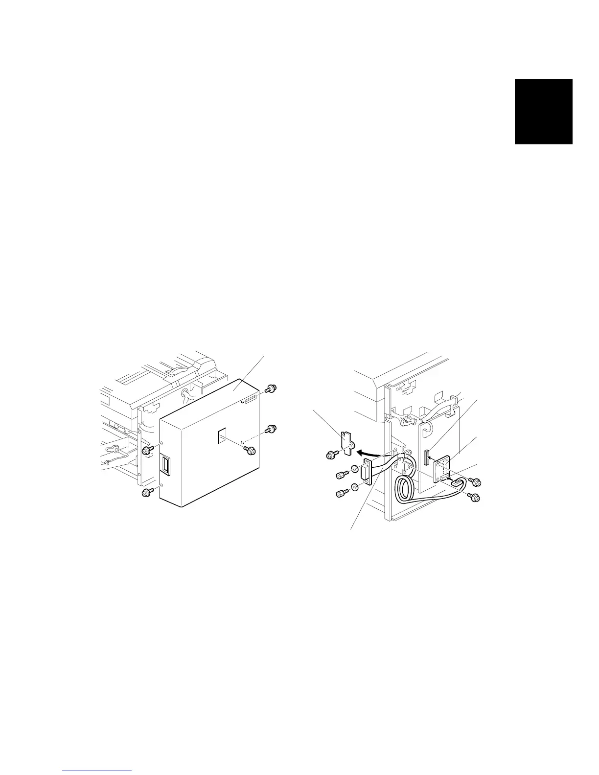
1. Remove the rear cover [A]. ( x 5)
2. Remove the I/F connector cover [B]. ( x 1)
3. Connect the I/F board [C] (accessories) to CN108 [D] on the MPU. ( x 2)
4. Attach the cable [E] (accessories) to the connector bracket. ( x 2)
5. Connect the connector [F] at the opposite end to the I/F board.
6. Re-install the rear cover.
C252I012.WMF
C252I011.WMF
[B]
[C]
[D]
[E]
[F]
[A]