FINISHER MAIN BOARD
G838 12 SM
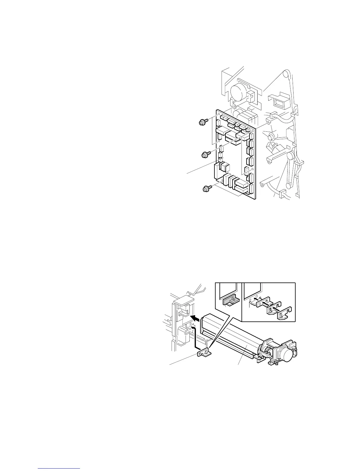
1.15 FINISHER MAIN BOARD
1. Rear cover ( 1.1.1)
2. Main PCB [A] ( x 6, All )
1.16 PUNCH HOLE POSITION ADJUSTMENT
To adjust the position of the punch holes in the paper feed direction, use the
appropriate SP mode.
To adjust the horizontal position of the holes, use the spacers provided with the
punch unit.
1. Rear cover ( 1.1.1)
2. Punch unit [A] ( x3, x5)
3. Spacers [B]
The punch position can be
adjusted by up to 4 mm using
combinations of the 3 spacers
provided with the finisher.
B352R206.WMF
B352R119.WMF
[A][B]
[A]
 Loading...


