Rockwell Automation Publication 5094-UM001E-EN-P - April 2020 189
Application/Wiring Examples for Safety I/O Modules Appendix C
5094-OW4IS and
5094-OW4ISXT Relay
Module Wiring Diagrams
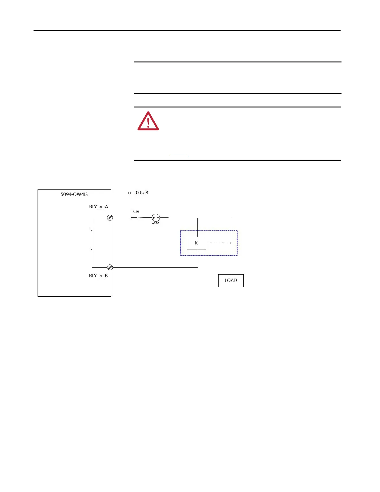
The following wiring diagrams show the relay output modules.
Figure 45 - 5094-OW4IS Module - SIL3, PLe, CAT4
IMPORTANT The Safety level shown in below diagram is applicable to module itself.
Connected device shall have their own status monitoring to achieve application
safety level.
ATTENTION: When you are using the relay to drive DC/AC inductive load, you
must connect a snubber across the load. Failure to connect a snubber across the
load (relay contacts) can result in generation of electromagnetic noise that
could disrupt nearby electrical equipment, including your 5094 FLEX I/O chassis.
See the Industrial Automation Wiring and Grounding Guidelines, publication
1770-4.1
SIL level and Category:
SIL3, PLe, CAT4
(Signal state change at least once a month)
SIL2, PLd, CAT3
(Signal state change at least once a year)
Fault Exclusion:
External Wiring fault
Other:
Qualified actuator must be used in the application
Fuse with proper rating should be connected to
prevent relay contacts from overload and short
circuit.

 Loading...


