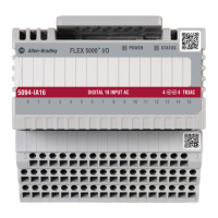
Do you have a question about the Rockwell Automation 5094-IA16 and is the answer not in the manual?
| Manufacturer | Rockwell Automation |
|---|---|
| Product Type | Digital Input Module |
| Series | 5094 |
| Number of Inputs | 16 |
| Input Voltage Category | 24V DC |
| Operating Voltage | 24V DC |
| Current Draw @ 24V DC | 100 mA |
| Power Dissipation | 2.4 W |
| Shock | 30 g |
| Vibration | 5 g |
| Isolation Voltage | 50V continuous |
| Enclosure Type Rating | None (open-style) |
| Operating Temperature | 0 to 60 °C |
| Storage Temperature | -40 to 85 °C |
| Relative Humidity | 5-95% non-condensing |
| Input Voltage Range | 20.4 - 26.4V DC |
| Wire Size | 0.2...2.5 mm² (24...14 AWG) solid or stranded copper wire |
Details compatibility requirements for modules and Logix Designer application versions.
Options to secure access to the I/O modules and control system by authorized users.
Describes the different types of FLEX 5000 I/O modules available.
Explains the controller's role as the owner of I/O modules in a control system.
Explains how to create and transfer module configuration using Logix Designer.
Lists critical precautions for the proper use of FLEX 5000 I/O safety modules.
Describes how FLEX 5000 digital input modules interface with sensing devices.
Details the capabilities of FLEX 5000 digital output modules for driving output devices.
Describes how FLEX 5000 I/O modules indicate data quality to the owner-controller.
Reduces the possibility of using the wrong device by comparing project definition to installed device.
Explains how FLEX 5000 digital input modules send data at a user-defined rate.
Allows adjustment of On/Off filter times to improve noise immunity in signals.
Monitors for loss of power at an input module point and sends a fault to the controller.
Covers topics specific to all FLEX 5000 output modules, such as state change times.
Defines how output modules behave when the connection to the owner-controller breaks.
Highlights features unique to specific standard output modules, such as time-scheduled control.
Describes features available on FLEX 5000 safety input modules, including suitability levels.
Details suitability levels for safety input modules based on SIL, PL, and Category.
Covers features specific to FLEX 5000 safety output modules, including suitability levels.
Explains the two types of point modes for safety output channels: Safety Mode and Safety Pulse Test.
Lists prerequisite tasks before configuring a standard FLEX 5000 I/O module.
Guides on adding new FLEX 5000 I/O modules to a Logix Designer project.
Explains how to edit common configuration parameters for FLEX 5000 I/O modules.
Shows available input filter time values for module points.
Lists prerequisite tasks before configuring or replacing safety I/O modules.
Guides on adding new FLEX 5000 safety I/O modules to a Logix Designer project.
Explains how to edit common configuration parameters for safety I/O modules.
Allows setting the RPI rate and Connection Reaction Time Limit for safety modules.
Provides steps for replacing safety I/O modules, considering safety network numbers.
Describes the SA Power indicator states and recommended troubleshooting actions.
Explains the Module Status indicator states and their meanings for troubleshooting.
Details the status indicators for FLEX 5000 DC and AC input modules.
Explains how to use Logix Designer features for troubleshooting module faults.
Describes the defined naming conventions used for module tags.
Guides on how to view module tags using the Tag Editor in Logix Designer.
Lists configuration and input tags associated with the 5094-IA16 module.
Details configuration and input tags for the 5094-IB16 module.
Lists safety input and test output tags for the 5094-IB16S module.
Provides wiring diagrams for safety pulse and safety modes of IB16S/SXT input modules.
Shows wiring diagrams for output modules in safety and safety pulse modes.
Presents wiring diagrams for safety relay output modules.
Lists calculated safety parameter data for IB16S/SXT digital safety input modules.
Provides safety parameter data for OB16S/SXT digital safety output modules.
Lists safety data for OW4IS/OW4ISXT safety relay output modules.


 Loading...