8-14 Serial Communications
1560D-UM051D-EN-P – February 2005
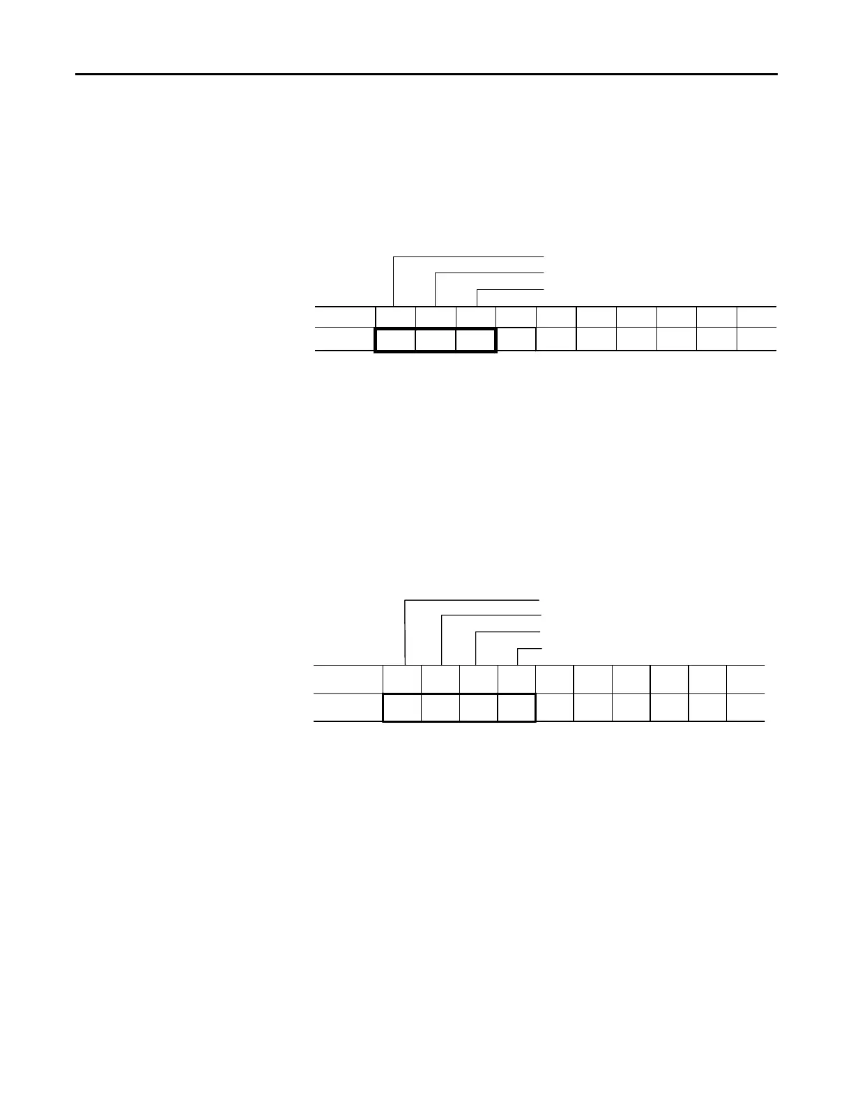
Remote I/O Examples (cont.) BT Control Buffer Layout – The following table maps integer files starting at
N10:0 with the associated M0 file location as defined in the sample ladder
logic program that follows.
BT Control Datafile
Address0123456789
N10:0
64 0
Bulletin 1203 communication modules use full slot addressing. Refer to the 1747-SN scanner manual
for complete details to determine a BT logical address.
This word is set by the ladder logic program. Refer to the 1747-SN scanner manual for Control Flag
Definitions.
Control Flags
BT Length
BT Logical Address
BTW Datafile Format – A four-word data file is required to accomplish a
"Continuous Parameter Value Read". For the example that follows, the
BTW Datafile will begin at address N10:10.
BTW Datafile
Message Length
PLC Decimal Value
Number of Parameter Values to Read
Starting Parameter Number
Address0123456789
N10:10 4 1 11 1
This is a fixed value, associated with the "Continuous Parameter Value Read" function.
Message Length
PLC Decimal Value
Number of Parameter Values to Read
Starting Parameter Number
Address0123456789
N10:10 4 1 11 1
This is a fixed value, associated with the "Continuous Parameter Value Read" function.
 Loading...


