Installation 2-5
1560D-UM051D-EN-P – February 2005
Power Connections The controller requires a three-phase supply and an equipment grounding
conductor to earth ground. A neutral conductor of the three-phase supply
is not necessary and is usually not routed to the controller. Three-phase
wiring will connect the controller to the motor.
Important: Refer to 1500-UM055B-EN-P for power/ground bus
location and cable routing for a Bulletin 1562D. For retrofit units
(Bulletin 1560D), refer to Figures 2.1, 2.2 or 2.3.
Line Connections
Load Connections
Line Connections
Load Connections
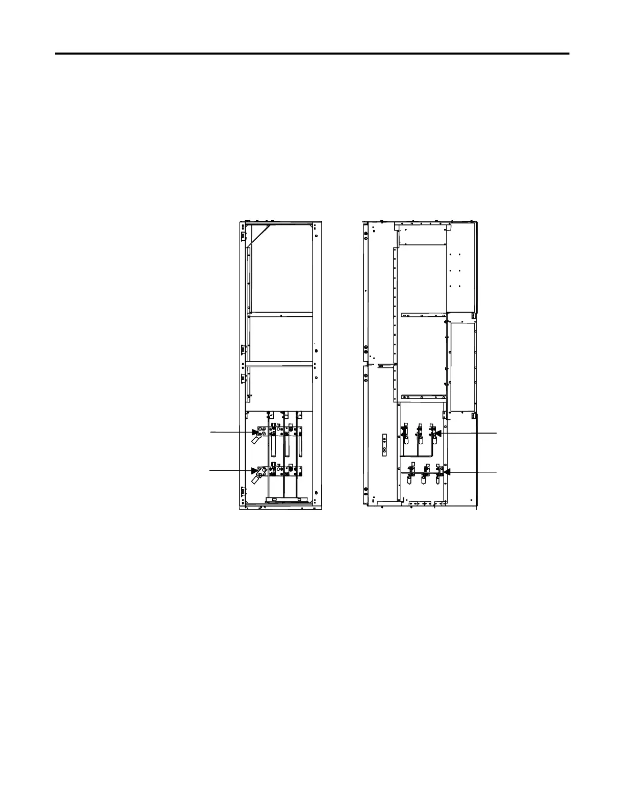
Front View RH Side View
Line Connections
Load Connections
Line Connections
Load Connections
Front View RH Side View
Figure 2.1 – Power Connections • 1560D – 180/360 A, 2400 V to 4160 V
Note: Bottom cable exit shown. Lugs may be oriented upwards for
cables exiting through the top of the cabinet.
Important: For 1503D, refer to applicable documentation from OEM for
installation, grounding, interlocking and wiring. This manual should be
utilized in conjunction with the OEM supplied documentation, and is
suitable for commissioning, programming, calibration, metering, serial
communications, diagnostics, troubleshooting, and maintenance of a
standard solid-state controller.
 Loading...


