2-22 Installation
1560D-UM051D-EN-P – February 2005
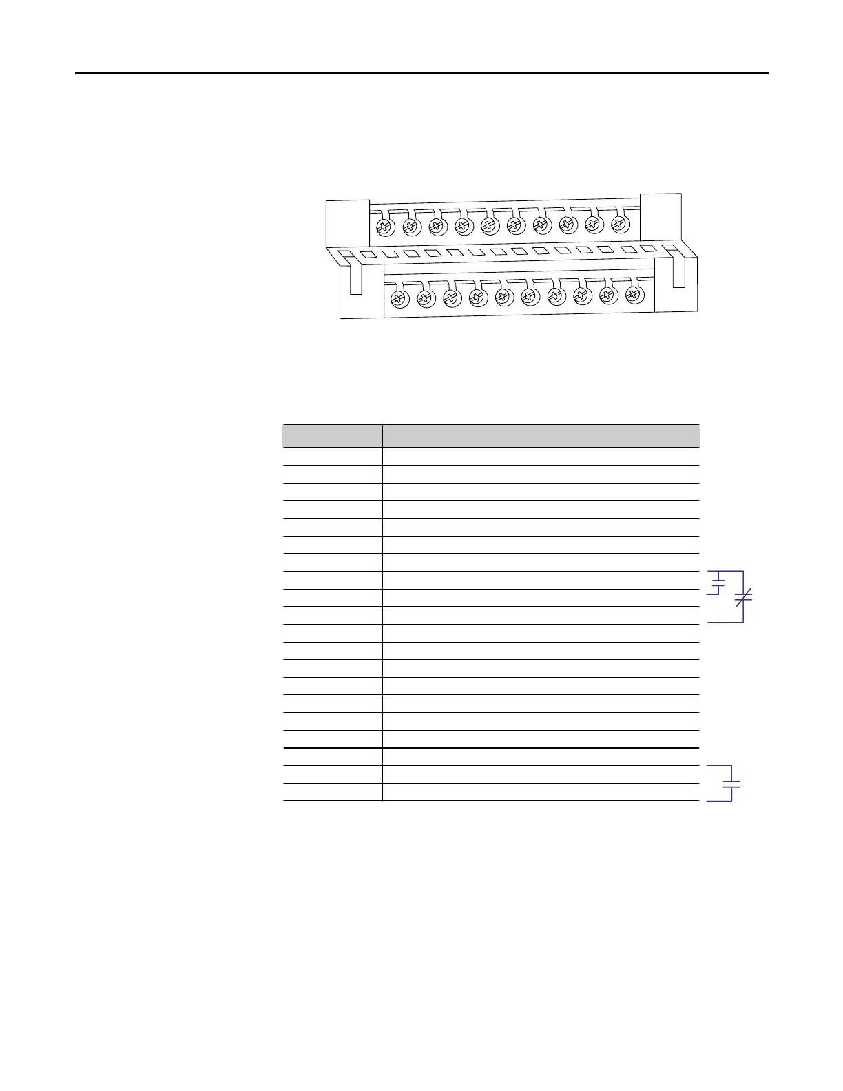
Control Terminal Designations As shown in Figure 2.9, the SMC Dialog Plus™ controller is equipped
with 20 control terminals on the front of the controller.
11
21
12
22
13
23
14
24
15
25
16
26
17
27
18
28
19
29
20
30
Figure 2.9 – SMC Dialog Plus Controller Control Terminals
Terminal Number Description
11 Control Power Input
12 Control Power Common
13 Controller Enable Input X
14 Logic Ground
15 Dual Ramp/Option Input X
16 Start Input X
17 Stop Input X
18 Auxiliary Relay Common
19 N.O. Auxiliary Contact #1 (Normal/Up-to-speed)
20 N.C. Auxiliary Contact #2 (Normal/Up-to-speed)
21 Not Used
22 Not Used
23 Not Used
24 Not Used
25 Converter Module Fanning Strip Connection X (Common)
26 Converter Module Fanning Strip Connection X (Phase A)
27 Converter Module Fanning Strip Connection X (Phase B)
28 Converter Module Fanning Strip Connection X (Phase C)
29 N.O./N.C. Auxiliary Contact #3 (Normal/Fault)
30 N.O./N.C. Auxiliary Contact #3 (Normal/Fault)
X Do not connect any additional loads to these terminals. These “parasitic” loads may cause
problems with operation, which may result in false starting and stopping.
Y When control power is absent from terminals 11 and 12, this contact will be normally open.
Upon application of control power, the contact will take the state, normally open or normally
closed, as programmed. Refer to Fault Auxiliary Contact on page 9-3.
Y
 Loading...


